Summary
I got inspired by a YouTube video I saw where Adam Savage created an infinity mirror using a rhombic dodecahedron. You can see the video here:
Well, I thought I’d do something similar, using this video as a guide. Notable changes from Adam’s design:
- Created a Cube instead of a Rhombic Dodecahedron, because I don’t know what I’m doing yet.
- Adam had a hard time shoving the LED light strips into the Dode and an even harder time making all the electrical connections. I solved this problem by creating a custom PCB for each edge, with terminals lined up so that GND goes down the middle of the PCB and VCC travels along the edges. Then you can flip the PCB any which way and it will still line up with its neighbors.
- This was a really good idea but my implementation was lacking
- To avoid the tricky part of sealing everything inside and having it be tight as well, I installed the lights in a wooden frame and then set the mirrors in the frame after.
- Initially the frame was going to be 3D printed but this turned out sloppy-looking and I found out my printer needs much better calibration.
Materials
- 6mm Baltic Birch
- 3mm Acrylic
- Black PLA
- Two-way stick-on film that you get to make windows block sunlight.
- Glues: Wood Glue, Hot Glue, Epoxy (2-part Gorilla Glue)
- PCBs, assembled.
- LIttle jumper wires to stick the PCBs together, and solder.
- Power connectors, VCC 5 Volts
Modelling
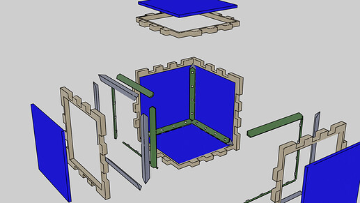
Modelling took place as an iterative process of drawing things up in Blender, trying to laser-cut (or 3D print) the box, inspect, and adjust the model. Eventually I arrived at this:
The idea is:
- Put the wood box together.
- Seat in these angled prisms, which will (a) hold the PCBs at 45 degrees to the cube faces and 90 degrees to each other, and (b) provide a lip for the windows when they are placed in the cutouts in the frame.
- Drill a hole in one of the corners to run a 2-conductor power wire. Install the PCBs, solder and test.
- Place the mirrored windows in the frame, and fasten with epoxy glue.
Considerations:
- All calculations came out of the assumed inner dimensions of the box (95mm).
- Windows were assumed to be 90mm x 90mm.
- OSH Park only manufactures PCBs that are wider than 1/4 inch so the PCBs were designed to be 7.62mm (0.3in) across.
- The prism rest provides a triangle 6.5mm tall, 6.5mm wide with a 9.2mm diagonal, ensuring enough space for both lip and board support.
- Did the rest of the math carefully to ensure a close fit, but allow for 1-2mm of wiggling and manufacturing tolerances. Interestingly, the angle 109.5 degrees comes up fairly often, which is the angle 2 hydrogen atoms make around a carbon atom in CH4.
Initial Assembly
- Laser cut the 6mm baltic birch. Use boxes.py with an inner dimension of 95mm, a window of 90mm, and a thickness of 6mm.
- Cut at 60/63/12 and 2 passes was just enough. Next time, set the speed to 10.
- 3D-print the PCB supports.
- Put everything in there and check for fit. If it does, wood glue it all together, dry, sand, and paint black.
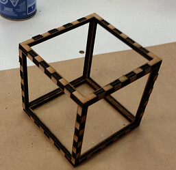
A slightly earlier version of the cube, while I was still figuring out the sizing requirements:
Electrical Design
The circuit is pretty straightforward. 5V pushes current through an LED and resistor, times 48.
Using LED “Inolux / IN-S85AT5UW / LED WHITE CLEAR 0805 SMD” which is cheap and bright and good for 5mA but I read the datasheet carefully and chose a resistor (180 ohm) that will push it closer to 10mA for extra brightness. It should be fine but we’ll see how that goes.
Total power dissipation should be about 2.5W, which is what I read a smartphone burns when sitting idle on a charger.
PCB was drawn up in KiCad and sized according to the dimensions we need. In hindsight, I should have created a custom footprint to have VCC go to each side of GND on the connections, rather than behind it. But, it was still symmetical and it worked.
I ordered one set from OSH Park which was $25 for the boards and another $25 for fast shipping. I ordered a second from JLC and they cost $5 for everything and it showed up only one day after OSH Park. I’m quite disappointed with OSH. They didn’t even include a sticker in the package!
Final Assembly
-
Laser cut the acrylic tiles, and carefully apply the mirror film to one side.
The mirrors in the drying tray: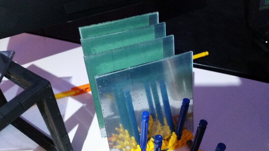
-
Attached the SMD LEDs and Resistors to the PCBs according to plan, using my rework station. Listened to Mark Twain audiobook while I worked.
The cube, ready for PCB insertion:
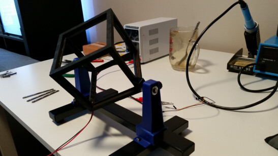
-
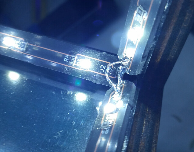
Inserted PCBs and kinda hacked together little jumper wires to connect each terminal on each corner to each other. Here, you can see the corner junction.
-
Powered everything on and left for a bit to make sure nothing burned out.
-
Installed the mirrors, carefully to check for alignment. Fixed in place with a dab of epoxy in each corner. I couldn’t figure out how to seal off the edges without making a mess.
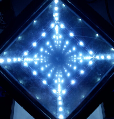
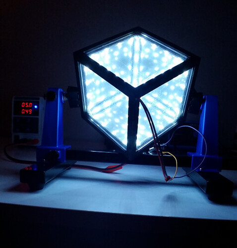
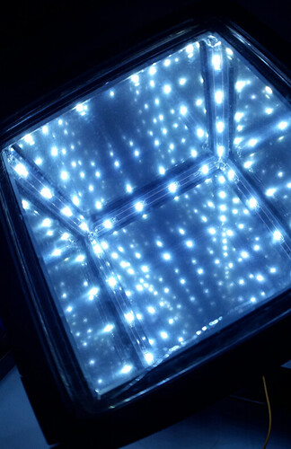
And it worked! Right now it looks like something out of Avengers. Next steps are to 3D print a stand of some kind, and paint the power cable black.

