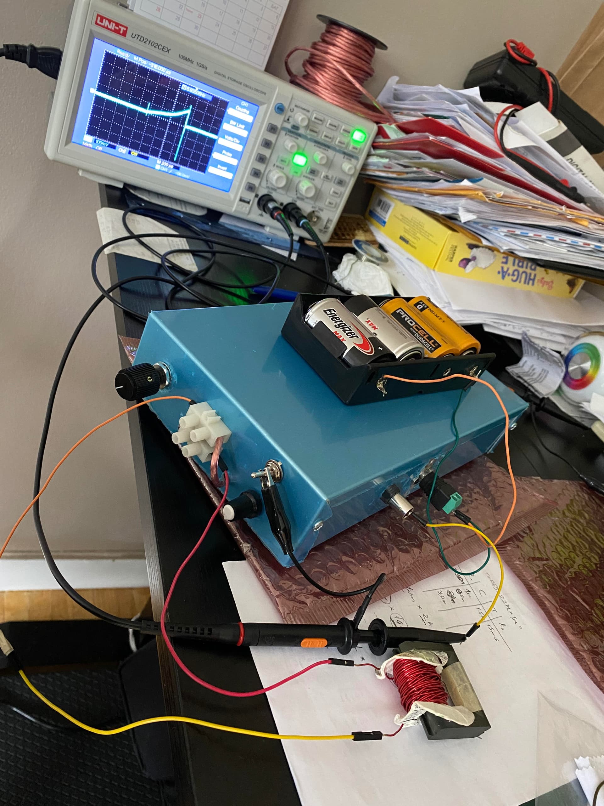
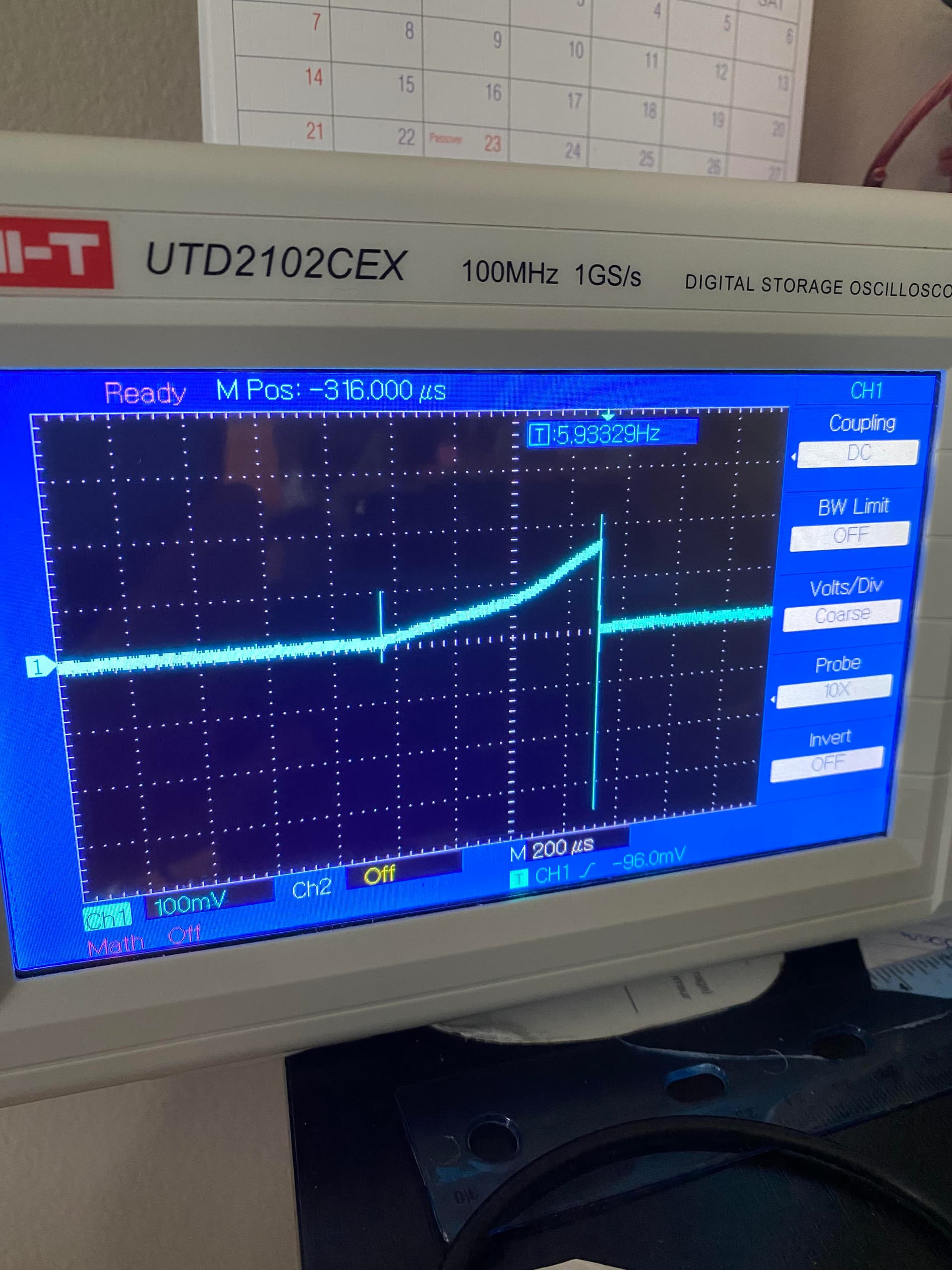
In a nutshell, what it does is send high-current pulses through the inductor under test. With 1% duty cycle it can pump as much as 10X the current normally supported by the wire, then the saturation knee of the magnetic core can be visualized using an oscilloscope. It can also serve to measure inductance.
As you can see, there are some modifications with respect to the original schematic:
i) simplified the circuit by using only one 555 ic for rectangular pulse generation and negated its output with a pnp transistor
ii) increased the C1 capacitance such that to provide enough charge for a triangular ramp of 10ms duration from 0 to 70 A, without losing more than 10% of its 12 V voltage
iii) re-designed the flyback circuit to handle 70A current without exceeding 40V drain-source voltage drop on the MOSFET
What should have been done but I didn’t was include an overload protection mechanism to turn off the MOSFET when the current reaches 70A. It works without it, but I have got to be careful not to exceed 70A through the inductor under test, otherwise the MOSFET will be fried.