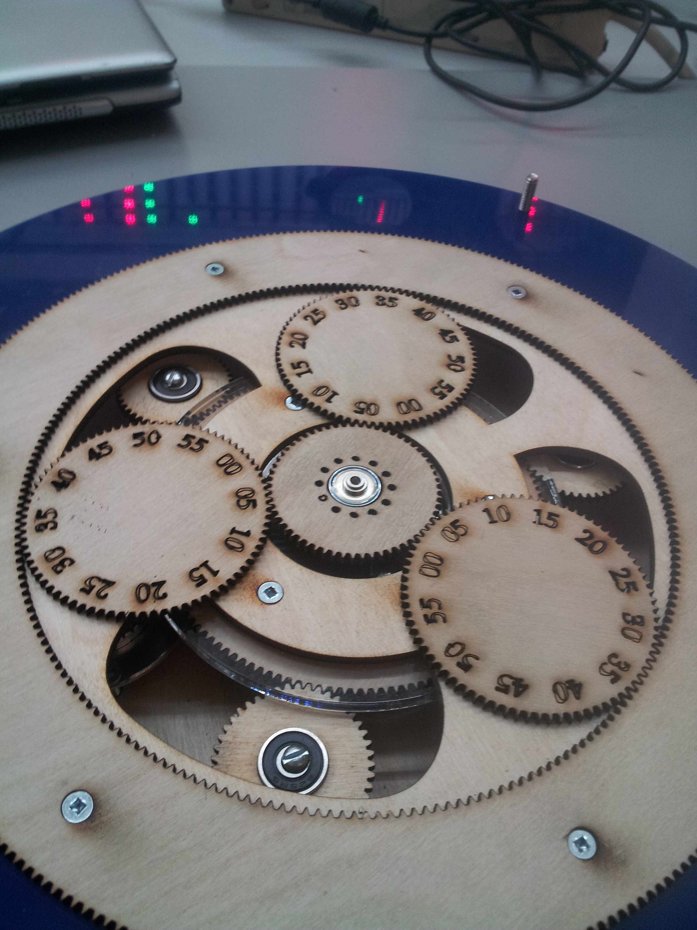
What software or procedures do hackspace members use when designing gears? I’d like to try my hand at lasercutting some planetary gear systems. I’ve seen tutorials on designing involute tooth profiles from scratch, but it seems quite laborious and I’m sure its been automated. The procedure isnt obvious for the tooth profile of the ring gear. Heres some gear porn in the meantime.
Paging Doctor @LoialOtter… Doctor Loial to the conversation, please.
I’ve used… uh… everything I could to design gears. The following list produces very good gears:
- Autocad (manual or with autolisp/other scripting)
- OpenSCAD (libraries available)
- Solidworks (personal favorite - numerically generated curves and so awesome)
- Python (scripts available)
- R (only if you already know it)
- Pen+Paper… but really really slow
What doesn’t work:
- Blender (someone will or has proved me wrong already)
- Lightwave (technically i did it but gah)
- 3d studio max (scripting only, might as well use python… does a better job too)
Okay, some info about gears. The most well known gear tooth profile is the Involute Gear. It has a number of amazing properties that have made it the standard used in 99% of the gears on the planet now [citation needed]. It's a tooth profile that follows the involute curve from a base circle which has a diameter so that the curve is at a specific incident angle as it passes through the pressure diameter (there are far easier ways to calculate this).
The involute gear is unique that it’s the only tooth profile that, at all positions of contact, the incident angle of the contact with the meshing tooth is a single angle. This angle is called the pressure angle and is one of the main defining values of a given involute gear (standards are 14.5, 20, 25 degrees… others may be used). Lower pressure angle produces, if i understand this one correctly, less friction and less pressure driving the gears to separate. Higher angles allow more power through the gear because the line of force goes further into the root of the tooth.
The outside diameter or addendum of the tooth is usually a fixed pitch-width out from the pressure diameter. The root or dedendum of the tooth is also a fixed pitch-width in from it. Normally these are about 0.6 for addendum and 1.0 for dedendum but can be less than that if you need a stub gear. These values are ratios of with of one tooth, so half the pitch.
That’s pretty much it for what may be different in a gear other than pitch and number of teeth.
Okay, the actual math is… interesting…
The actual involute curve is easiest drawn with polar coordinates:
Cartesian is still possible:
![]()
![]()
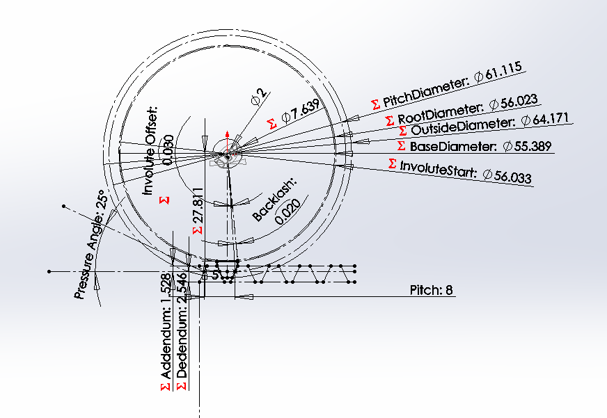
and so this is what my solidworks curve is:
-“BaseDiameter@Sketch1”*SEC(t)*SIN(-(tan(t)-t)+“FullInvoluteOffset@Sketch1”)/2
-“BaseDiameter@Sketch1”*SEC(t)*COS(-(tan(t)-t)+“FullInvoluteOffset@Sketch1”)/2
where t is between: arccos(“BaseDiameter@Sketch1”/“InvoluteStart@Sketch1”) and arccos(“BaseDiameter@Sketch1”/“OutsideDiameter@Sketch1”)
… which looks a lot more complex than it is.
2 Likes
I have used inkscape to make “simple” gears before. It works but is not ideal.
The involute gear profile makes sense for circular gears, but I’m not sure how it applies to ring gears in planetary gear systems.
There’s another way to draw an involute than just with a formula though. What the involute curve IS is just the curve the tip of a thread or string follows as it’s rolled off a bobbin. Given that, there are some special rules to it, one is that it’s movement is always perpendicular to the tangent from the root circle. Given that rule, you can draw it using a square after drawing the root circle.
This is an approximation, but has proven useful a number of times where I didn’t have full formulas.
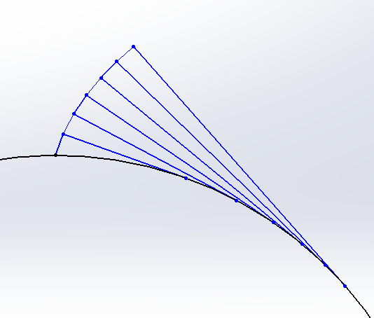
Each of the long lines are tangental to the circle and perpendicular to the short line segment closer to the circle.
1 Like
The teeth can be made for each specific pressure diameter. This would mean that either side of a tooth have a different involute curve but since they’re always synchronous to the matching teeth, as long as the pressure diameters matched between faces, that’d work.
1 Like
Inkscape’s gear extension is pretty great. I built a planetary clock a
couple years ago with nothing but that and napkin math.
Teeth in ring = teeth in sun + planet + planet
Then the relationships between diametric pitch, distance, etc.
If you actually want to simulate it, then Gearotic is the best, if overkill
for most applications.
2 Likes
We should ask Matthias if it’s OK for us to buy one copy of his program and install it on a shared computer in the space.
3 Likes
There’s a third way… … which is probably the most universal as it’s the only way I know how to make non-involute gears. Note that this method is… uh… resource expensive… but will always produce perfect results.
The involute gear is the only gear that when you have a gear with an infinite number of teeth (I.E, it’s pressure circle is a straight line… or more normally it’s called a Rack), the profile is a straight trapezoid-shaped tooth. This feature means that if you roll a form against a set of teeth in the exact pattern the gear would mesh with a rack, and remove all the material that interferes with the teeth, you get a gear.
Other gears, to make them mesh, you do the same thing but starting with the first gear, which cuts the profile of the rack, and then you use the rack to cut the profile on the matching gear.
Sorry, missread. The ring gear is an inverted spur gear… you simply do a negative operation of a spur gear against a larger cylinder and it gives you the ring gear. The only thing you have to do is reverse your addendum and dedendum lengths (draw your spur gear with an addendum of 1.0 and dedendum of 0.6).
Same thing applies to all other gears as well from what i can tell…
Oh, here’s my gear design… uh… file:
All definitions are within the first sketch within the first feature. Edit that and it’ll adjust itself completely
The ring gear is the same profile. The only issue you may have is that the
tooth depth may need to be deeper to prevent binding on the planet gear’s
teeth. I never had that issue, I think it may only crop up when rings and
planets were not so different in size. It’s been awhile since I did the
research.
edit:
my resume ![]()
2 Likes
It’s not cheap (nor that expensive really), but Gearotic will create just about any kind of gear and gear train that you can imagine - http://www.gearotic.com
1 Like
That looks like a cool tool. Even outputs G-Code for milling!
Sent email to Gearotic to find out the cost of the license for VHS (Hoping for a non-profit, educational discount)
1 Like
I actually have a license for Gearotic already that I was going to donate. It was planned for the CNC mill’s PC, but I’d be OK with installing it on the Solidworks machine instead so that the whole membership can access it. However, if Gearotic is willing to donate a license to VHS, I’ll stick to that plan and the donated license can go on the Solidworks machine instead.
4 Likes
OK, should I contact the Gearotic guy or is someone else looking to do so?