I am once again asking for your sage insight regarding the development of my teensy synth project.
I’m using the teensy audio shield which has both line outputs as well as a headphone outputs, which is great. However, the headphone output on the audio shield uses its own internal virtual ground of about 1.65V, which means the headphone virtual ground can’t be connected to any other ground. So plugging the headphone output into the input of an external amplifier with a different ground reference could damage the teensy audio shield chip. So these outputs are only meant to be connected to headphones–nothing else.
This is a problem because I am making this as a kit that eventually other people could build and use, and it’s very likely someone will plug the headphone output into an amplifier or some other external gear, instead of just using the line outputs. I’d rather just fool proof the design so both are safe.
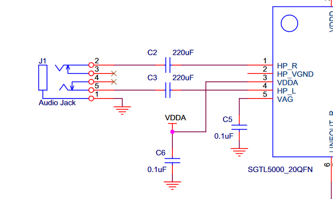
Soo, I read the manual for the audio shield chip (SGTL5000) as well as trying to find info on other forums and it looks like I can maybe just do this configuration:
But my question is more in the specifics. Like should I use certain types of capacitors over others to avoid more phasing? Is there anything I could do to improve on this application to reduce any DC popping? Also I only have studied basic DC electronics concepts, I know how capacitors work but it’s unclear to me what they are actually doing in this application? Are they creating a DC Bias or protecting the headphone amplifiers, or both? I don’t really like adding circuits into my design that I don’t fully understand. Any help would be greatly appreciated, thank you so much!
Series capacitors on a signal path allow higher frequency signals to pass through, but they block the DC component.
It’s similar to how an speaker crossover circuit works to split an audio signal into different frequency ranges for the subwoofer and tweeter for example. How to Build a Speaker Crossover Network
It looks like the teensy audio shield already has series capacitors on the line out signals, so yeah adding the capacitors to the headphone output will probably serve the same purpose.
I don’t know exactly what types of capacitors work best, but in my experience I’ve found that larger ceramic SMD capacitors (specifically the multi-layer type >10uF) have a weird quirk: they’re slightly piezoelectric, which means that if you pass an audio frequency across them they’ll actually make noise!
The virtual ground will only pose a problem if both the virtual ground and real ground are coupled at the external device. This might occur if for example the end user uses a USB output of their PC to power your device, and also attaches the audio output to the line in on the same PC. Attaching the virtual ground itself to a different (isolated) ground isn’t a problem, but what is a problem is if it gets shorted to the ‘real’ ground through the external device. Just to clarify the problem.
Do you want to provide line outputs or HP outputs or both?
The alternative circuit should work, but it is somewhat difficult to define its behaviour because the impedance of the load is unknown.
For a DC blocking capacitor, once the load is attached, what you have is a filter with the C in series with the R||L of the headphones. Naively (with the R component only), this is an RC high-pass filter (which always blocks 100% of DC), however headphones will also have significant inductance which will add a pole to the response, in other words the result will be a non-flat frequency response, varying depending on the headphones that are connected. The impedance components of the headphones will also vary with frequency further complicating things in this application. I’m not sure how pronounced this effect will be with the shown values and ‘typical’ headphones, it might be negligible. You will also get a pop when the device is turned on, as the transient (to the virtual ground) appears on the headphone outputs.
As far as capacitor types, in this application, electrolytics are going to be the only practical option for reasonable frequency response, since headphones have quite low impedance, the required value to achieve low frequency response is too high to use ‘better’ types.
Awesome, thanks for explaining the issue better. And yes, often external audio interfaces for computers are running off USB power only, so it’s likely my device would get plugged into this and also be USB powered from the same laptop. (My device will however have the option to be powered without USB but it’s optional)
Both.
Totally. Which I assume will shift the roll-off point of the high-pass filter and sort of muddy/phase more less of the low frequencies depending on the headphone impedence? This would be acceptable. I just want the headphone output available for monitoring only, not recording, so as long as it’s not terrible I’m happy. Mainly I’m just looking to protect the SGTL5000 codec chip on the teensy audio shield.
Someone on the Teensy forums suggested going up to 1000uF for the capacitors, I assume which would lower the general roll-off point of the high-pass filter? Is there such thing as too high a capacitance for this application?
I’m confused regarding this point. I would be leaving the virtual ground on the audio chip unconnected and then be grounding the headphone jack ground to teensy ground like in the schematic I provided. Would there still be popping when the unit is turned on? (popping is fine honestly, just curious about this)
Finally, mega noob question here, but if i’m using polarized capacitors in series with the RL which direction would they be oriented?
this explains so much. I always wondered why I could ‘hear’ USB signalling from my gaming rig, when the motherboard had the audio path isolated and airgapped specifically to prevent amplifying non-audio signals. I’ll wager that the southbridge caps were leaking acoustically. not the first device from which I’ve wondered why I could hear digital signals either.
TIL!
Both the high-pass rolloff as well as the magnitude and position of the node introduced by the inductance of the headphones will move around. It’s not an uncommon design though, so I assume the effect is manageable. The alternative is to create a bipolar supply and drive the headphones +/- the system ground, but that’s a significant complication. In fact, avoiding the large output coupling capacitors is almost certainly why this chip has a virtual ground in the first place, it allows the output to be DC coupled and reduces the BOM cost.
1000uF seems like it would be a reasonable value. The main downside of a larger capacitor is that it will take longer to charge up to the DC bias at turn on, so you’ll see DC for longer on the output. Might result in worse ‘popping’ and a bigger risk of damaging the headphones. Audio probably isn’t high enough frequency for it to matter, but larger caps also tend to have worse frequency response.
What I mean is that the headphone outputs of the chip will have a DC bias point at the virtual ground, in other words when there is no signal, the headphone outputs will be at the virtual ground voltage. Since that’s not equal to the system ground, the coupling capacitor will see a transient that will ‘get through’. Depending on the design of the DAC chip, you might also get transients here if it turns off the amplifier or virtual ground when there’s no output. Plugging in headphones while the device is on is probably also not great; adding a large-ish (10k i guess) resistor to ground after the capacitor might help.
The DC will be + at the headphone output (which sits at the virtual ground when idle), and the other end of the capacitor eventually goes to ground via the load, so the + of the capacitor should be towards the amplifier.