TIL you can use F360 CAM to generate DXF files that compensate for your laser kerf!
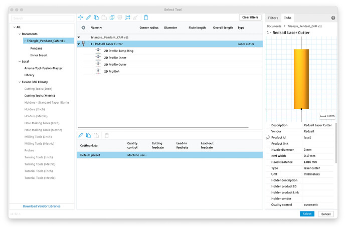
You need to set up a tool in your F360 Tool library for your laser specifying the kerf. I determined my kerf to be 0.17mm. (see below)
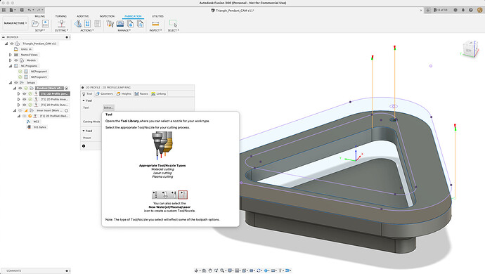
Then you select the Cutting operation in your CAM Setup and select your newly created Laser Cutter Tool
The only CAM operation for cutting is a 2D profile operation.
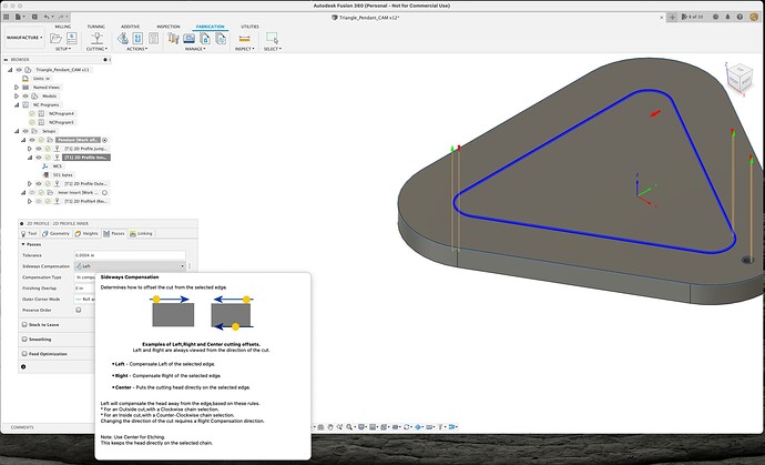
With F360 CAM toolpaths you can choose to cut outside your line (exterior to object), inside your line (interior to object) or on the line for etching. You do this by selecting sideways compensation (Left,Right,Center) in the passes tab.
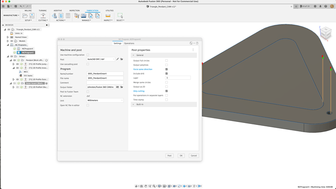
Once you’ve generated your NC Programs then you choose post process and save it as an AutoCAD DXF file which you can then import to laser cad and use in the normal fashion.
The really cool thing with CAM is you can add tabs and create offsets using the “Stock To Leave” option in the passes tab for your path. This is really handy for creating nice press fits.
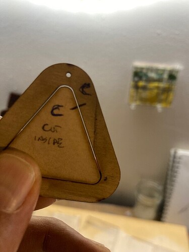
The pendant with the interior cutaway. Notice the larger than usual gap as the full object size is preserved. i.e. cutting on the inside of the line for interior cutouts.
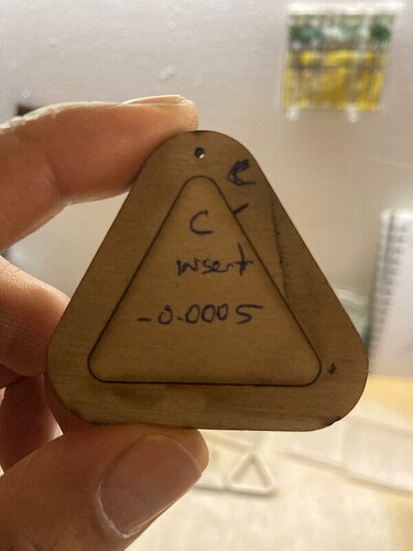
The separate light press fit insert with the ‘Stock to Leave’ set to -0.0005
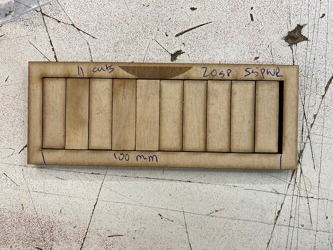
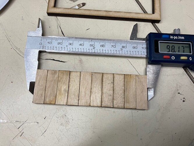
Your Kerf will change depending on material being cut, material thickness, laser speed and laser power. I determined my Kerf for 6mm ply cutting at 20 speed ,55 power by cutting 100mm rectangle in 10 sections or 11 cuts and measuring the resulting width with callipers and subtracting from 100 and dividing by 11. My kerf worked out to be (100-98.17) / 11= 0.17mm
Two useful videos I watched to do all this were.
and
Happy Lazering!
