Hi I am trying to interrogate a microprocessor’s EEPROM and potentially change it.
It appears there is a foot print for an spi header on the board.
I just dont know what tools I need to interrogate the chip.
If anyone has any ideas feel free to share, thanks
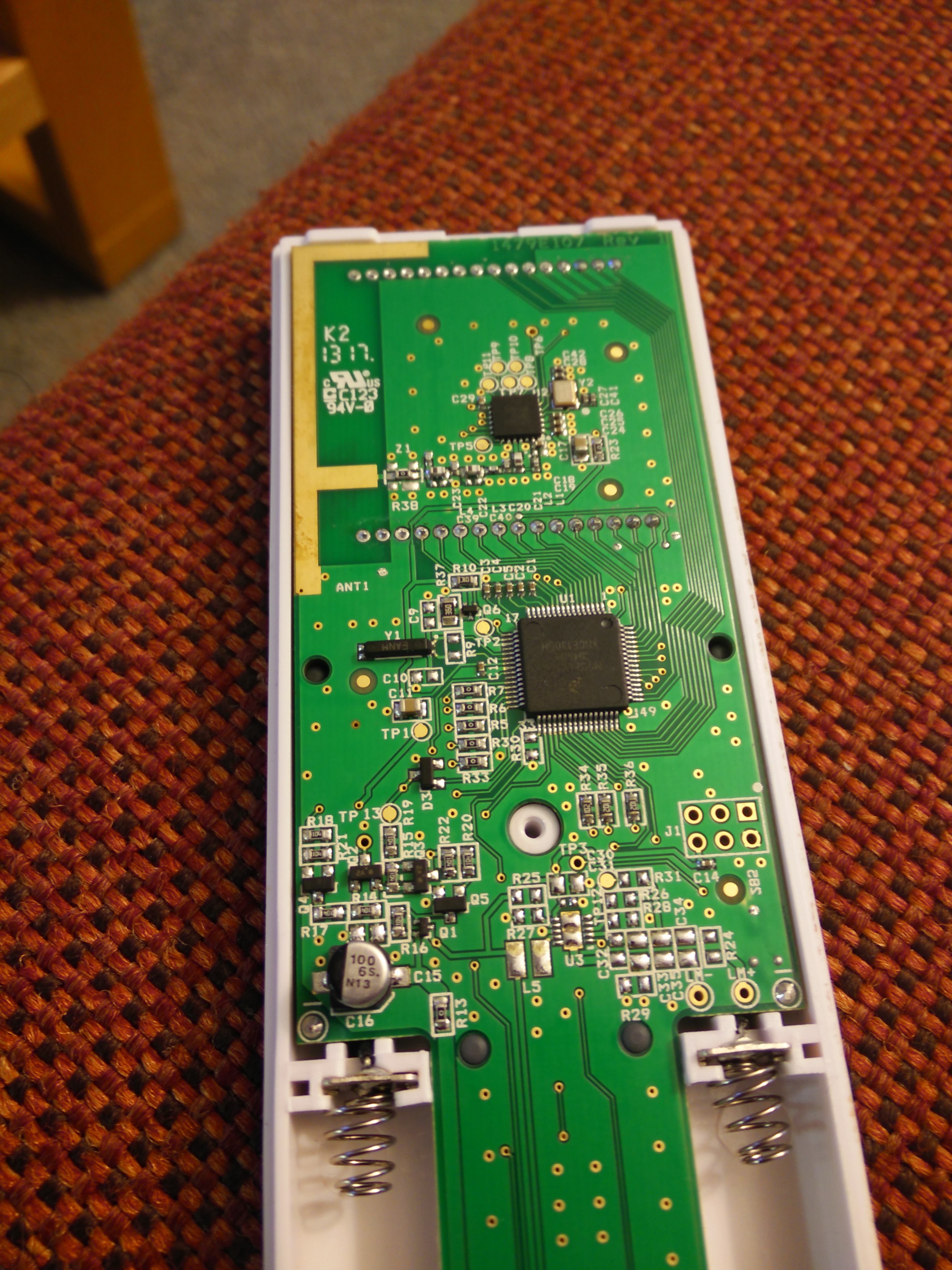
The chip in question is a M9S8LL16C
Here is a picture of the chip and board in question
Not really, I had to buy one of these for lectures for answering questions. I wanted to see how it worked, also wanted to see if I could change the hardware id which is apparently in the EEPROM
You need a BusPirate! VHS has one now. Currently it is in the dropbox. It
should allow you to listen/intercept/communicate with an SPI (or UART, or
I2C, or whatever) header.
If you use it, please mount it to a board! And store it in some visible
place that makes sense.
Please hack all the iClickers! I hate how they’re treated as disposable items and have as much resale value as a used textbook because the school demands you get a new version every year or two. And most teachers don’t know what to do with them beyond taking attendance.
I don’t know much about what you’re trying to do, but I think generally the round exposed discs of copper, marked TP#, are test points and may be most of what you need to monitor or reprogram the chips. If anyone knows better, I’d like to hear.
Does it do two way communication? It looks really complex to just be sending a button press and an ID.
I’d listen in with an SDR and see how it communicates too, as well as the above suggestions of reading the pins. You can just scope it to get a basic idea of the communication data, before you bus-pirate it.
It doesn’t support ICSP or standard programming interfaces like JTAG, but rather a single-wire “background debug interface”, which does look like the pin is going to that J1 header (hard to say as it’s going to a via then disappears). Figure 18-1 on p329 of the reference manual lists a 6-pin connector that is most likely what J1 is.
Yes, multiple choice questioning during lectures is what they’re purported to be used for, but it’s really just a way to get an additional $40 out of every student. Many students end up with 3 useless (out-of-date) iClickers by the time they finish their degree.
Rsim thanks for the data sheet!
I will look into that 6 pin connector you mentioned.
Tom, this is used for answering multiple choice questions in a lecture setting. But for the 50 bucks I paid for it, I figured I might as well get it to do some more interesting things.
I have ordered a software radio so my plan is to try and decode whatever it is transmitting. I’ll post any results I get.
Could you post better front and back pictures of the PCB?
The communication between the flash and microcontroller will still be one
of those protocols posted above and very reversible. The datasheet for the
flash chip should tell you.
If you’re going to try and reprogram the microcontroller itself, it might
be pretty easy to brick the device if you’re not able to back up the
firmware somehow.
There also might be a serial->RF driver chip somewhere? Big maybe there,
but it would be a lot easier to snoop on the serial portion before it gets
turned into RF.
Did you ever get anywhere with this? I’ve been trying to do the same with an iClicker 1, which has firmware that is more accessible - you can just dump it using the AVR-ISP pads. I’m interested in building my own compatible device using one of these modules. Does VHS have any SDR equipment I can use to sniff the iClicker’s communications?
Kinda like what I posted above, but sniffing the wireless stuff is way harder than sniffing the same communication on the PCB itself, but before it gets transmitted over the air.
Large pictures of front and back may be good for identifying the potential attack vectors.
Are you trying to learn how it works or trying to clone the devices? If you can dump the firmware already, then you can already clone them and there is no further need to reverse engineer it.
This is another page that you may find interesting:
However, if you already have the firmware, R/E the radio signal is IMO a waste of time as you would gather more protocol details from the software itself.