[FIXED] Laser was down due to burnt out laser tube

You’ve got my permission. It sounds like you know what you’re doing and will be safe. Please report back with what you find!

I believe we left it back near the laser cutter on the floor. Please return it when you are done.

Thanks, will peek around, but won’t actually attempt repairs today. Just a scouting mission for what parts are being used and how, so I can look up some datasheets. If I find anything unusual, I’ll let you all know. BTW, do you know if VHS has a resistor dummy load to take place of the laser tube while testing power supply?

1 Like

Take lots of pictures!

1 Like

Yes, I have seen a few large wattage resistors and an adjustable 10ohm 50watt potentiometer as well. If you can’t find them pm me and I can meet you at the space.

Also, it’s worth pointing out that the laser’s power supply died a few months ago and it was replaced. I believe the old power supply is in a box labelled power supplies under (or near) the microscope bench. That means you would have two power supplies to play with.

I have some 40KV wire if you need some for testing as well.

1 Like

Do we have the “speeds and feeds” of the power supply handy? Maybe a photo of its spec plate? Never mind, I can click links!

Just for fun I googled [co2 laser power supply schematic] and there’s a lot of DIY action if anyone is feeling brave. :slight_smile:

1 Like

Photos of our (dusty) JLD80W laser cutter power supply:
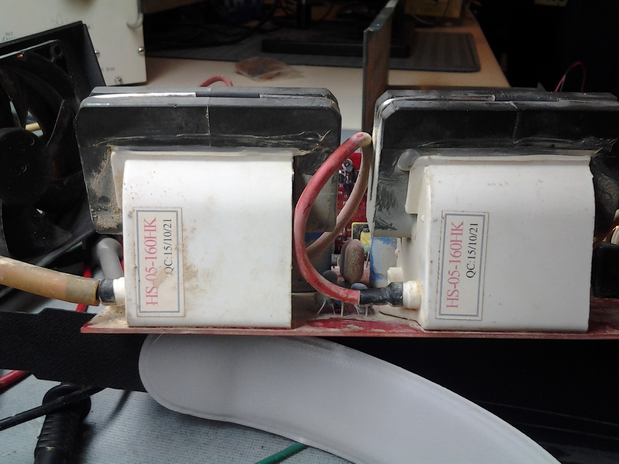
Below, dual Flyback transformers with main 22KV laser tube output (anode) wire at bottom left:

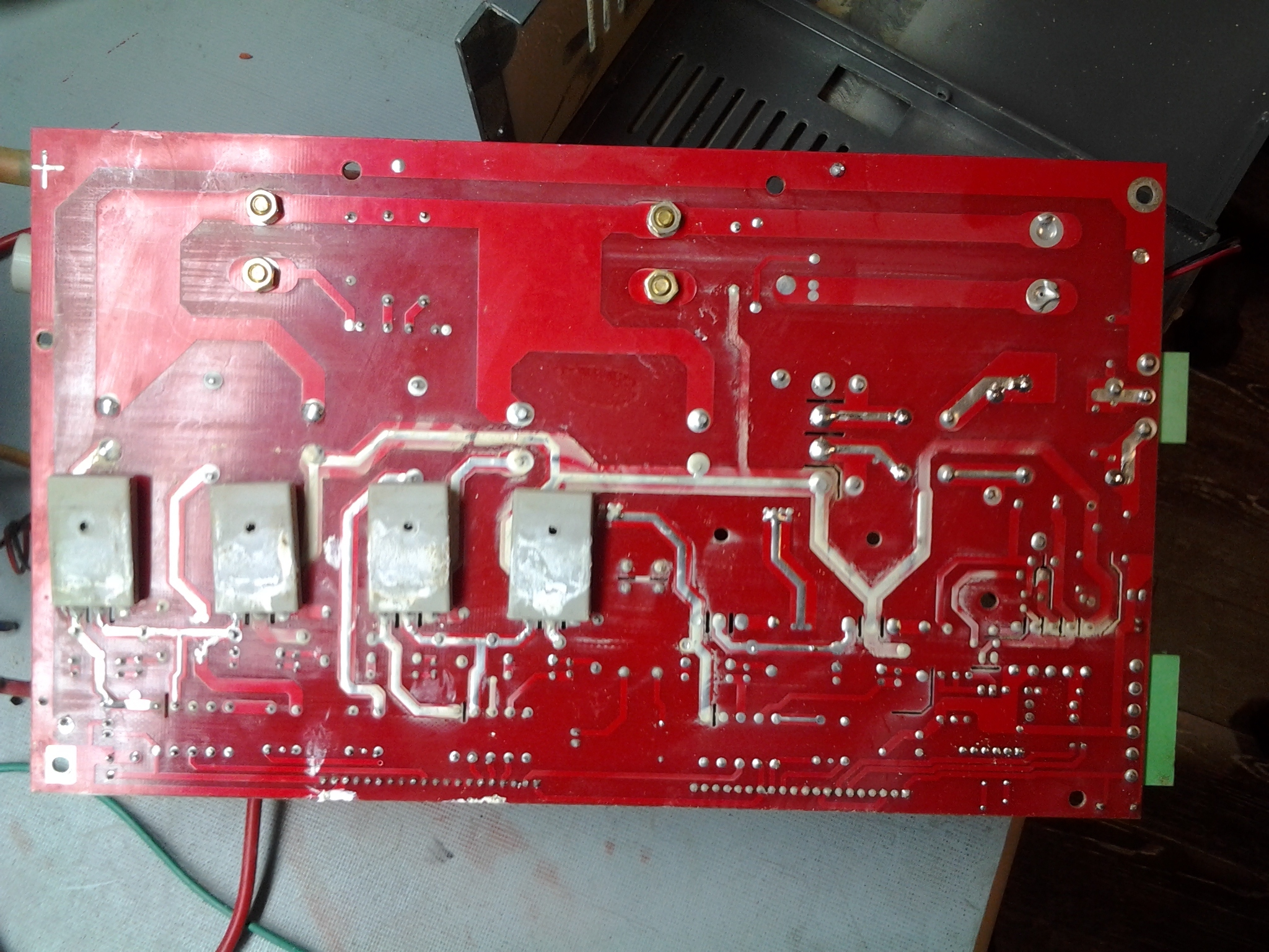
Below, bottom of power supply board showing 4 main switching MOSFETS that drive the flybacks. The white residue is normal. It’s thermal compound that helps transfer heat to the outer case :

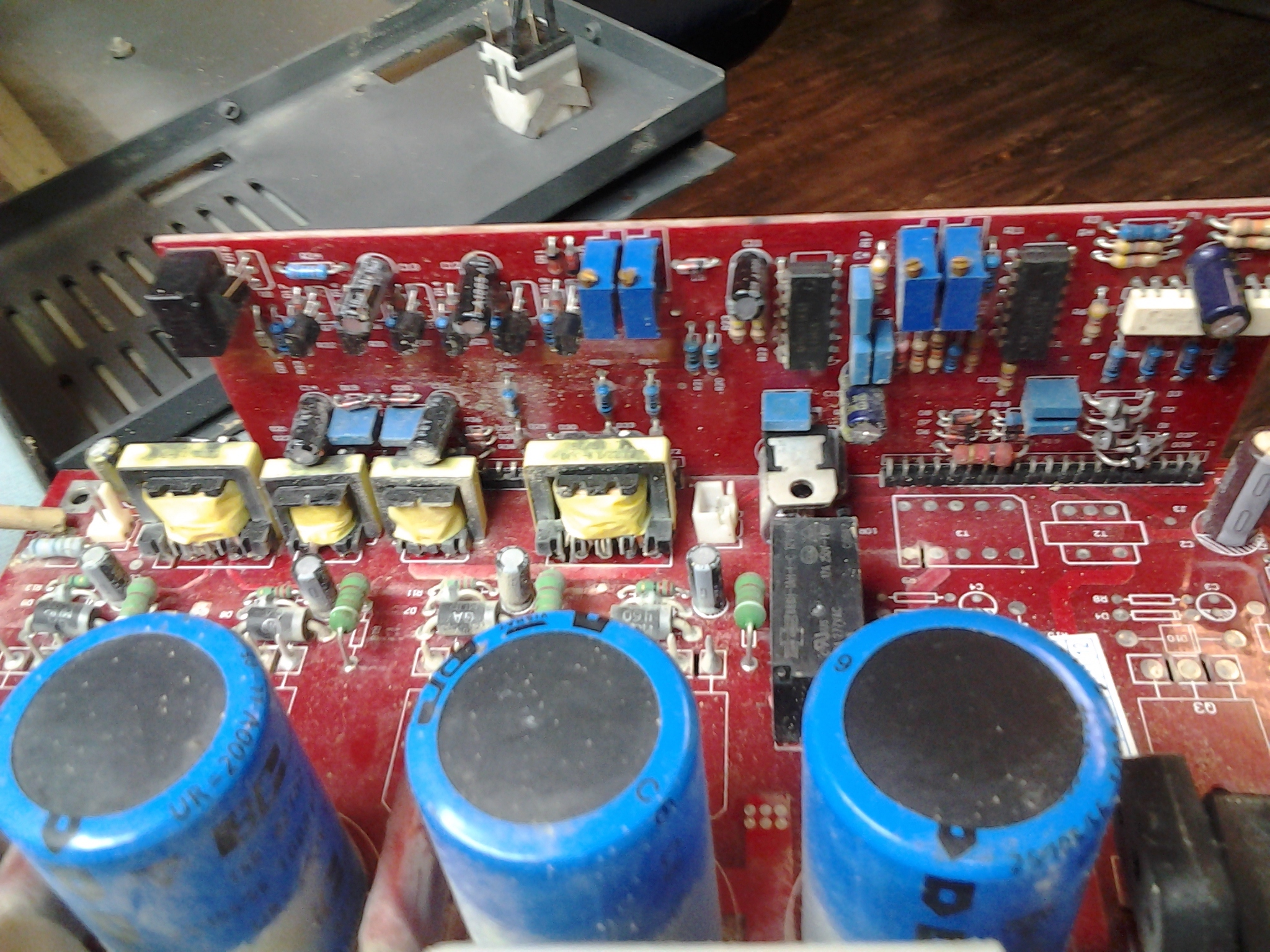
Below, Side view showing daughter board, the logic control “brains” of the power supply and (current?) calibration pots in blue near top:

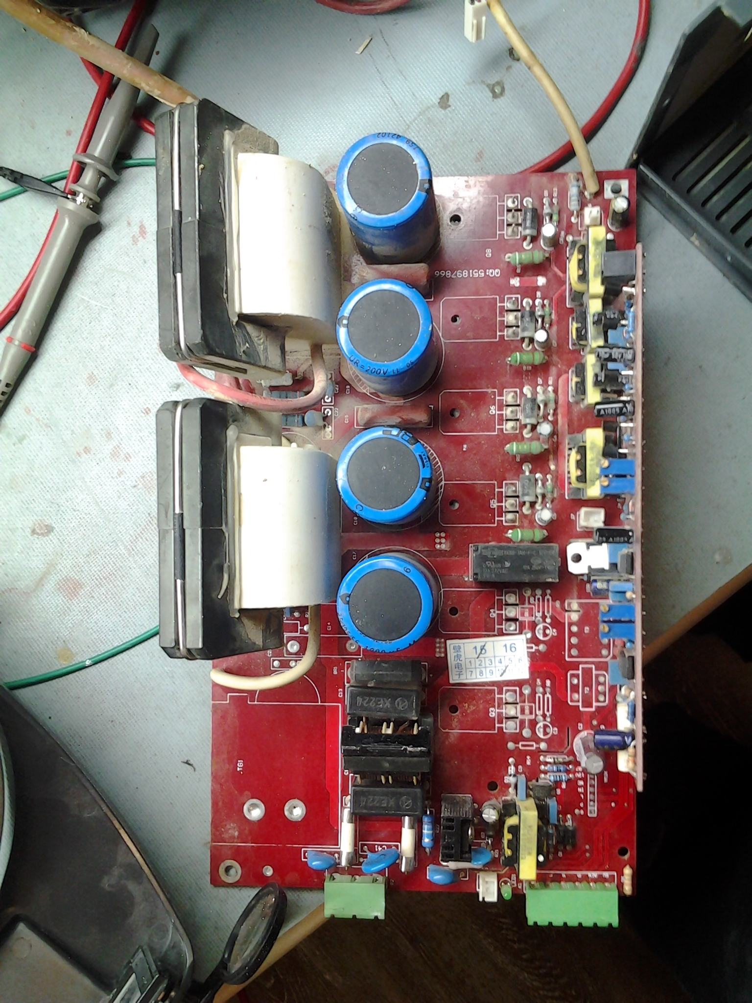
Below, Top down view of main PS board showing flybacks on the left and the big blue filter capacitors that feed them with DC (rectified) mains power The four black lumps below them are the main bridge rectifier and the LC line filter capacitors and inductor. Below them are two ceramic power fuses (white) and the RF suppression caps (small blue) and control logic wiring connectors (green).

So far, no obvious visual signs of physical damage such as burning, arcing, blown caps or cracked solder joints. Will do more in depth testing at next opportunity. Will any key holders be at VHS tonight? I don’t see any calendar entries for this evening.

5 Likes

Nice!

The opaque fuses on the bottom there seem like like a low-effort target.

Fuses both tested ok on meter.

I’m an electronics n00b, but A couple of pins (in the daughterboard connectors?) look like they might be bridged (green underlines in image), plus the general dirtiness might be hiding problems.

Presumably very little of the dust will contain conductive materials, but you never know, you know?

Wow this is so awesome. Thanks for the pics. I’m excited to see what you
try next.

@DerrickA4mag if you want to come down to the space and work on the HV power supplies, PM me, I can meet you there and open up for you

1 Like

Thanks Hector,
I appreciate your offer to open the space. Would some time this afternoon, or this evening, be ok? An hour (or more) advance notice would be best. Am in Burnaby, so it takes about an hour to hop on the skytrain, and walk to VHS.

Derrick

I plan on being there after lunch and leaving around 6pm if that helps.

1 Like

Ok, thanks to Hector and Mike, it sounds like someone will be at the space, so I’ll aim to arrive at 1:00pm today.

1 Like

Will PM on my specific plans, looks like my lunch just got pushed back to 12:30

Laser filtration System.

My question / suggestion.

If we are using a filter box, then we should be using a furnace fan with enough pressure / suction to draw air through the filter. The booster fan I see has high CFU, but low pressure. Is it able to draw air through the filters? I suspect not?

Afaik the issue with our filtering system is that we are missing a condenser prior to the filters. The filters do not absorb the fumes, only physical particles (dust). The fumes being what causes the smells. While the existing filter would make the air seem cleaner as the smoke particles are filtered out, it does not stop the vaporized compounds.

If we were to install a condenser (a humidifier system appears to be sufficient according to my research) then the vaporized particles would turn solid again and either be trapped in the humidifier mesh or get filtered out by the particulate filters.

The above is based on my research of blogs and other laser cutting forums.

I also agree that you can never have too much airflow, the less time the fumes spend near the optics the less condensation build up we will have on them.

Update

The new PSU arrived, and we installed it, and got the same symptoms as before. Even when bypassing all other controller circuitry, there is no evidence that the tube is firing at all. This means the problem lies in the (brand new) power supply, the (newly installed, but purchased last year) tube, or the small amount of wire between them.

We’ve followed these steps, and I’ve been corresponding with the manufacturer on how to troubleshoot this further, but my time is pretty limited.

@DerrickA4mag & @hectorh: this means there was likely no problem with the old power supply. I noticed it’s now in pieces. I put all the pieces in a bin under the laser cutter. Could you put it back together?

The water chiller had a couple problems resulting from disconnecting/moving it during the laser tube replacement. That has all been repaired.

1 Like

In case you aren’t sure what to look for:

Perhaps check the low voltage control pins to the p/s are enabled and firing ok. The enable on my laser is gated by the door switch, the laser on switch and the water flow meter. Perhaps the water flow switch is disconnected?

1 Like