Electric bike build

Hi. I’m a new member, and my current project is to build a new electric
bike.

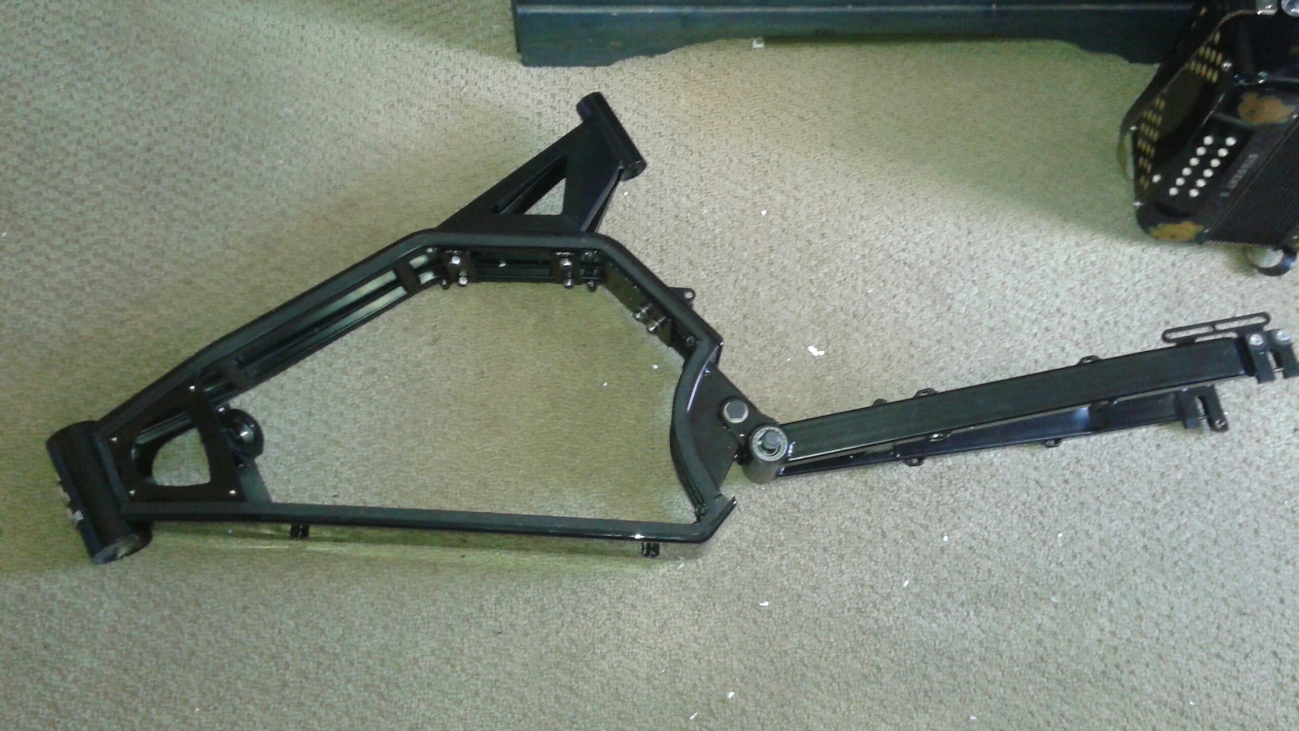
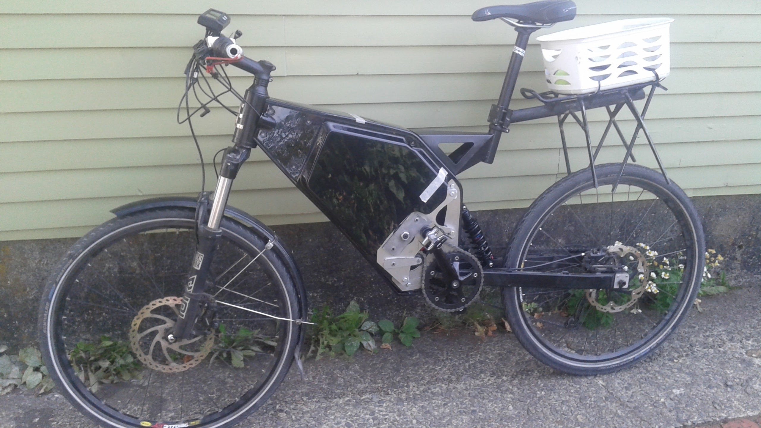
I’m basing it around this frame, which is made of steel and specifically
for DIY electric builds.

The large space inside the frame is for the battery and controller. The
frame is intended for use with a powerful hub motor in the rear hub, but I
will instead use a smaller mid-drive motor, inside the frame triangle.

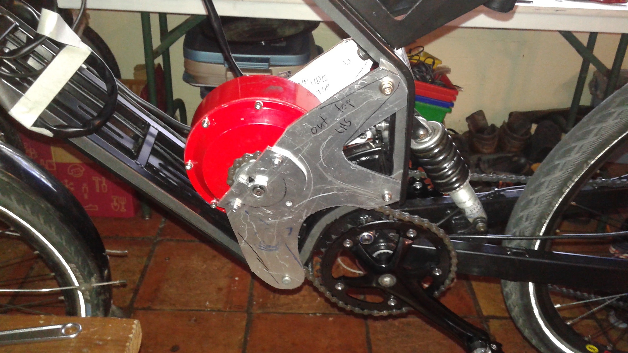
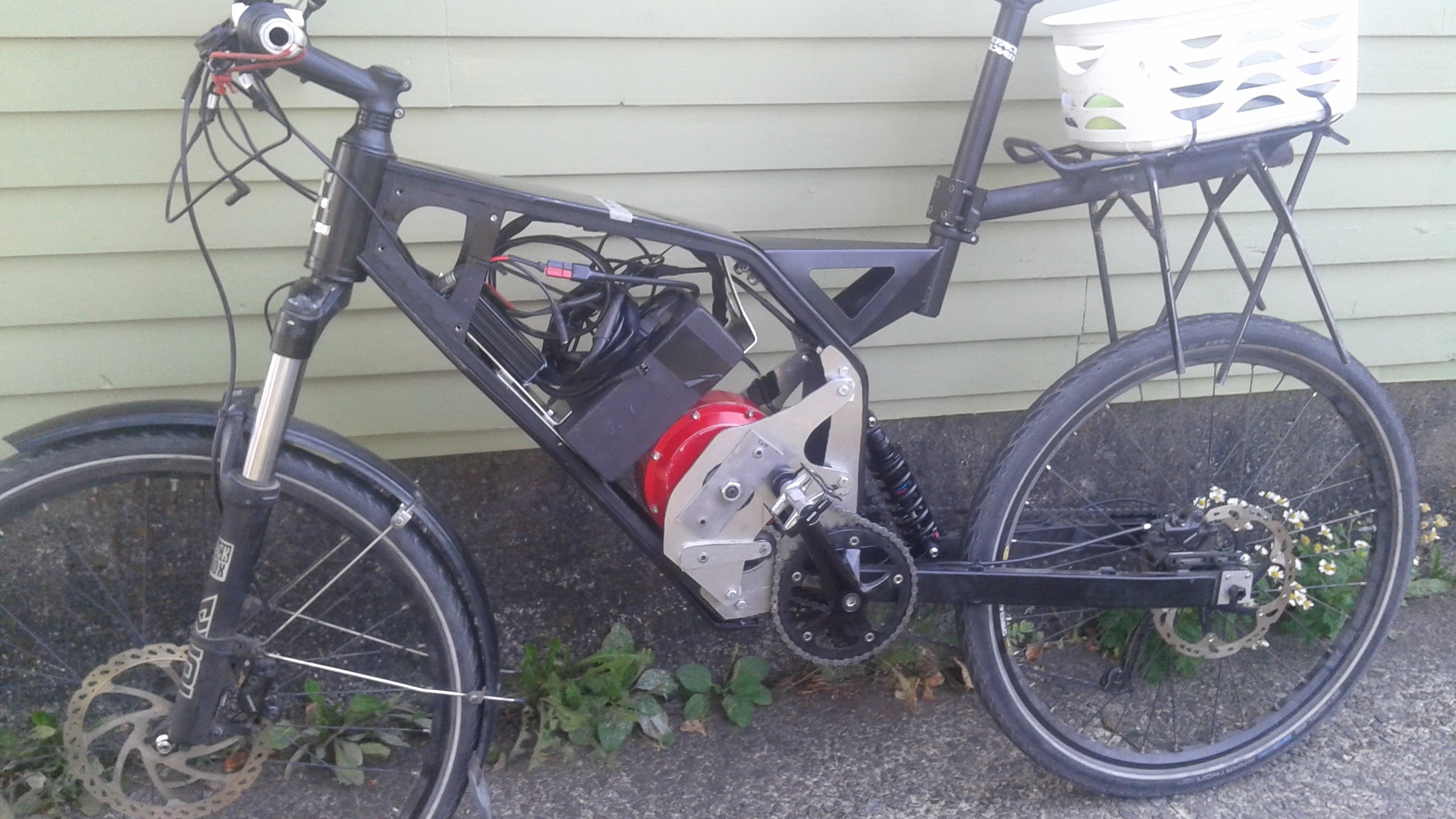
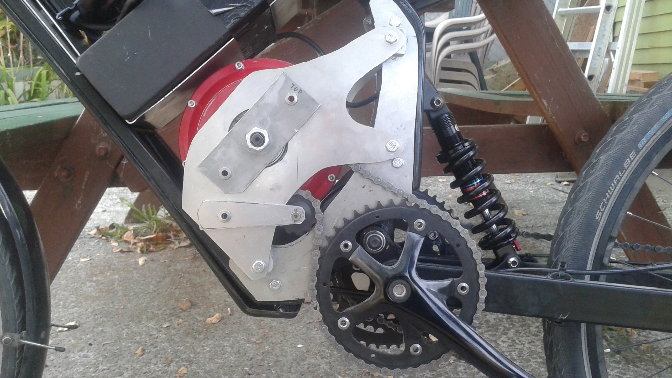
The picture below shows the rough arrangement I want for the motor. As the
(red) motor rotates, it turns a small freewheel, which drives the crankset
via a short chain.

If you look closely, you’ll see that the motor axle is held by a small
aluminum plate, that bolts onto the larger 3-arm plate. This smaller plate
will have to be made of steel in the working version, since there is a lot
of torque on the motor axle (60 Nm). The manufacturer recommends using
steel plate that’s 5-6 mm thick.

The hardest part of this project is to cut the 10 mm-wide slot in this
steel plate, for the motor axle to slide into. The only way I can see to
do it would be to use a milling machine. (If anyone has a better idea, let
me know!) I haven’t used this machine before, so will need someone to show
me how it works.

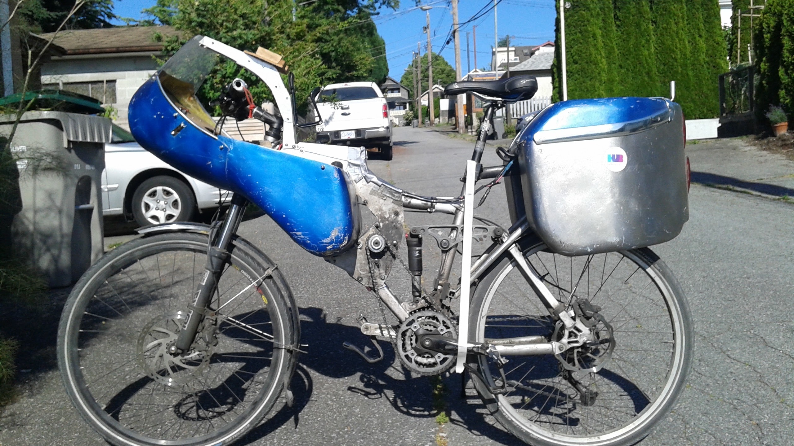
For some background information about what this bike is for, I’ll show a
couple of pictures of my old bike, recently dismantled. (The frame was
aluminum, and had gotten too old to be safe.)

It had a mid-drive motor as well, although smaller and much noisier. The
new one is larger, and more powerful as well as quieter. I used it for
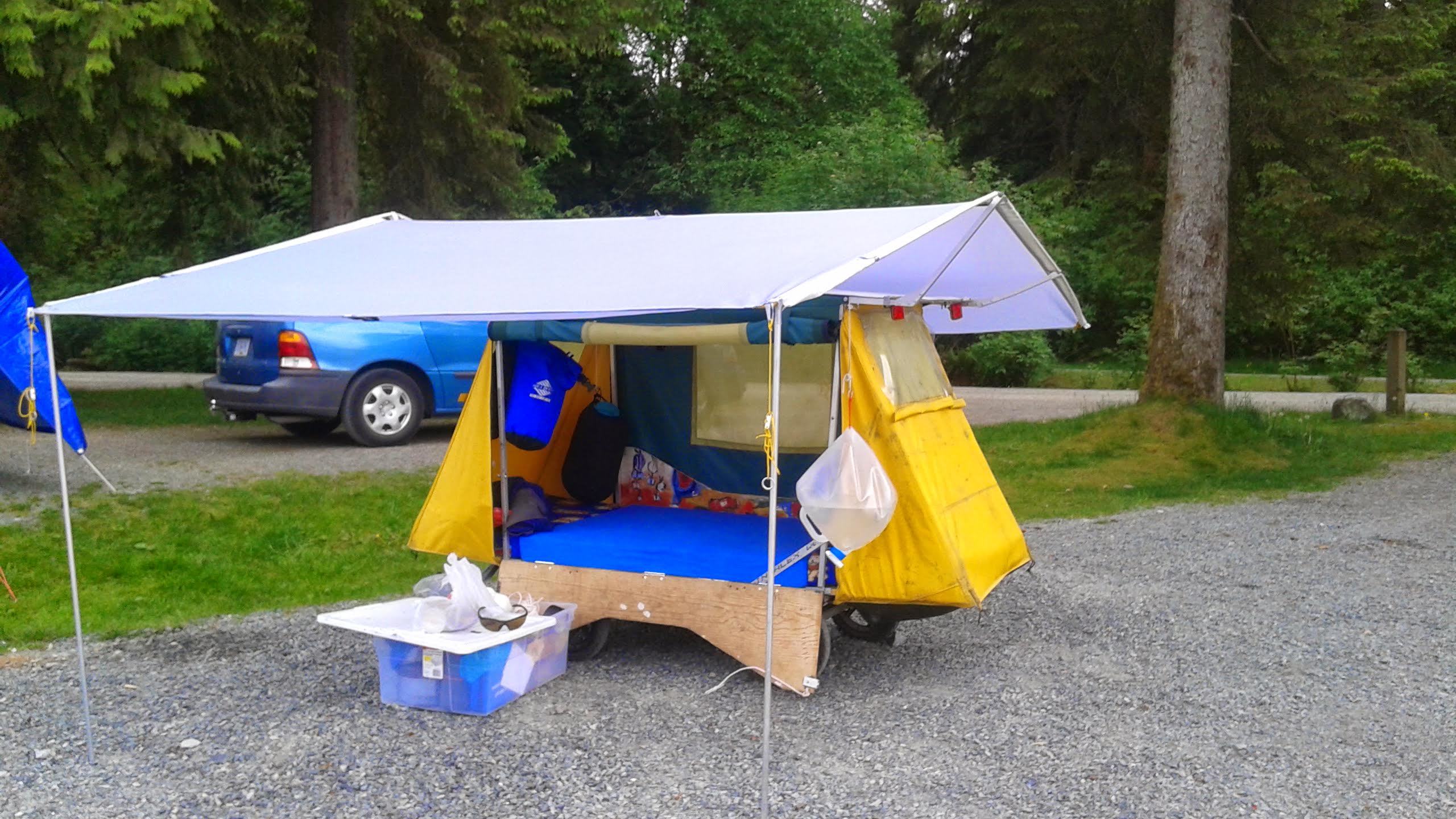
commuting, shopping, and touring. When touring I would often bring my
camping trailer to sleep in.

The old bike was barely able (If I’m honest) to tow the trailer over rough
ground, and up the steepest hills. The new one should be much better, as
well as far more durable.

Thanks for reading, and let me know if you have any ideas, or can show me
how to use the milling machine!

5 Likes

On viewing this post that I just made, I see that the pictures are all at the end, and in wrong order. Sorry about that! The last two pictures show my new build, the first ones are my old bike that I’m replacing, and the trailer that still needs towing.

You have an e-bicycle powered “fifth wheel” trailer, now that is AWESOMENESS!

1 Like

I’d love to come check this out in person!!! Any chance you’ll have it at the space in the not too distant future? Thanks for sharing!

Yes, I’d like to bring the bike in soon to do some work on it. I still haven’t found anyone able to show me how to use the milling machine though,

How thick is the steel plate, and does anyone know if our bandsaw (with the right blade) would be able to cut through it? We also have some hacksaws, which would probably do the job and be just as fast as setting up any of the power tools. Just make sure you have the right blade there as well.

The steel is 0.188" thick, i.e. 3/16 inch. You can cut it with a hacksaw, but the slot needs to be very precise, around 10.1 mm wide. I can’t even cut a straight line with a hack saw. I think the bandsaw would be a possibility, with the right blade (at least 18 tpi, maybe higher). I could clamp a straightedge to the base as a guide, for a straight cut, but getting the width just right would still be difficult I think. I guess I’ll try it with some scrap if no better idea comes along. Thanks.

Yeah, and if you need it to be precise, you could do a rough cut with a hacksaw and then carefully file it from there.

My electric bike is up and running now, though nowhere near finished, so I’m posting an update.

Here’s how the bike looks right now, and it rides very nicely. I’m happy to be towing my camper around again, and quite a bit faster than before up the hills. The side plate hides the details, so here’s a picture with it removed:

The black block in front of the (red) motor is the new battery, a 50V, 10.25Ah NMC lithium ion. (Bought from EM3ev in Hong Kong.) The small box in front of that is the Grinfineon 20A controller. There’s a lot of extra wire right now, but I plan to get them shortened.

The two biggest problems so far (now happily solved) were cutting the torque plates and keeping the chain at the right tension, despite the movement of the suspension swing arm.

The solution to the latter was discovered by chance, and I still haven’t exactly figured out how it works. I thought I’d need a spring-loaded chain tensioner, to take up the variable slack in the chain. But I actually have a fixed tensioner. Here’s a close-up.

The tensioner (small pulley between the motor sprocket and chain ring) is on a movable arm, but the arm stays fixed once adjusted. Somehow, with the pulley in this position, the geometry of the setup is such that the chain tension stays good despite the swing arm movement! This location was discovered empirically, by accident, so I don’t even know if it’s optimum. I haven’t found a clear explanation of why such a position even exists. Any ideas?

(My best attempt is to say that, although the distance between chainring and sprocket increases as the suspension compresses, which would normally tighten the chain, the bending angle of the chain by the pulley gear decreases at the same time. As the lower half of the chain straightens out, that section shortens, which compensates for the increased chainring-sprocket distance. The two effects cancel out, leaving the chain tension unaffected. ??)

My attempts to fit a sprung and swivelling tensioner into a very tight space were driving me crazy! Believe me when I say I was ecstatic when simple geometry came to the rescue!

Next up is to make new front panniers and fairing, in order to get back more of the functionality of my old blue bike. Time to glue together the styrofoam sheets, and start carving.

3 Likes

fixed chain tensioners are used on a lot of agricultural equipment.
Basically tensioning is empirical, until the chain stops excessively
flapping. Excessive flapping can cause the chain to come off the sprocket.
Don’t over tighten the chain.

Agreed. A chain isn’t really too loose until it falls off! The top side of the chain run stays tight in use because the sprocket and chainring are pulling it in opposite directions. The lower side is adjusted to be a little loose, but the runs of free chain (between gears) are so short that there’s no noticeable flapping. The clearances to the aluminum plates are also small, so certain potential lateral movements are prevented.

Curious on your cost of parts and materials and your estimated labour for
this project? What did you reuse from the old bike vs new items?

Yes, here are my costs to date. The frame and battery cost each include about $150 USD in shipping (ouch!)

Frame: $778.62
Battery: $731.37
Rear shock: $140
Rear wheel: $147.00
Motor kit (motor, FW, controller, CA computer, throttle, cranks, charger): $1,305.82
Sheet aluminum: $44.75
Seat post clamp : $7.34
Rear derailleur, brake cable + housing: $64.40
Seat post: $30.24
Brake hose and fittings: $35

Total : $3,284.94

I was able to reuse the front fork, front wheel, handlebar and stem, brakes (apart from hoses) and pedals. Probably saved at least $400 there.

The labour is hard to judge, but has been substantial. I could make a second bike in a couple of days, I guess, but there was a lot of figuring out with this one.