Background
In March I upgraded my Bike to a zoomy e-bike using a Grin Conversion kit. Do check out Grin if you haven’t heard of them, they’re a local Vancouver company that builds products which are super modular and very DIY.
Long story short, my bike now has a 36V Li Battery that is connected to the Grin Cycle Analyst. It has a 5.5x2.1mm Barrel Jack that is directly powered by the Battery.
This is almost 500 Wh of capacity at my disposal! I’ve always had lights that make me visible, but never lights that illuminate the road. Those are usually $$$, and have a high power consumption, resulting in low battery life. Could I make my own?
Goal
Build a front light for an e-bike that is powered directly from the e-bike battery.
There’s a few challenges…
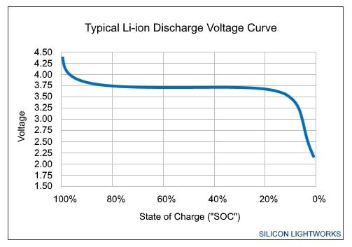
- The voltage from a battery pack is quite variable as a result of the discharge characteristics of a Li-Ion Battery. While the nominal voltage of a cell is 3.6V, the voltage when fully charged is 4.2V and discharged voltage is 3.2V. When 10 of these cells are connected in series, the voltage can vary from 32V to 42V. I would need to find a way to down convert this variable voltage to fixed output.
-
Vancouver is humid and wet AF. The LED enclosure needs to be sealed/potted in such a way that any internal electronics are protected.
-
Bike Lights can blind oncoming cars/pedestrians if improperly designed. Conformity to StVZO, a German Bike light Standard can prevent this from happening.
I started off by tackling #1.
Design
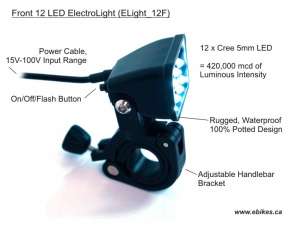
Since I didn’t want too much scope creep on this project, I relied on an existing device as a predicate to guide my design process.
Grin has these Battery-powered lights with an extremely wide input voltage range (12-100V). The light used 12 Cree 5mm LEDs for 420,000 mcd of luminous intensity. A quick parametric search on Digikey revealed that these were C503B LED’s with 33,125 mcd intensity each. These had to be the ones.
While Grin probably wanted a single light/SKU to work across their entire battery range, my input voltage range was only between 32V and 42V.
Connecting the LED’s in series and Parallel
When an LED is forward biased (emitting light), there is a voltage drop across each LED. The C503B’s have a voltage drop of 3.2V per LED.
If I connected all the LED’s in series, I would require a supply voltage of 38.4V, which falls right within my input range. As such, I would need a buck-boost converter topology to supply this voltage.
Instead, I chose to connect 4 LED’s in series, and have 3 parallel branches, which requires a supply voltage of ~13V and a current capacity of 60mA (20mA per branch)
Finding the right DC-DC converter
Very few DC-DC converters had the wide input range I was looking for. I limited my search to TI, since their converter product portfolio is very good, and they’re really nice with samples.
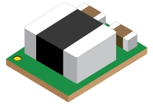
After much searching, I came across a cool module - the TPSM265R1
- 3V-65V input
- 1.2V-15V output @ 100mA
- 2.8mm by 3.7mm (THIS IS TINY!!)
- Since most of the circuitry including the inductors and the IC were already integrated on the module, I only needed 4 passives to add this module in to my circuit!
Quickly put together a PCB with this chip on Eagle
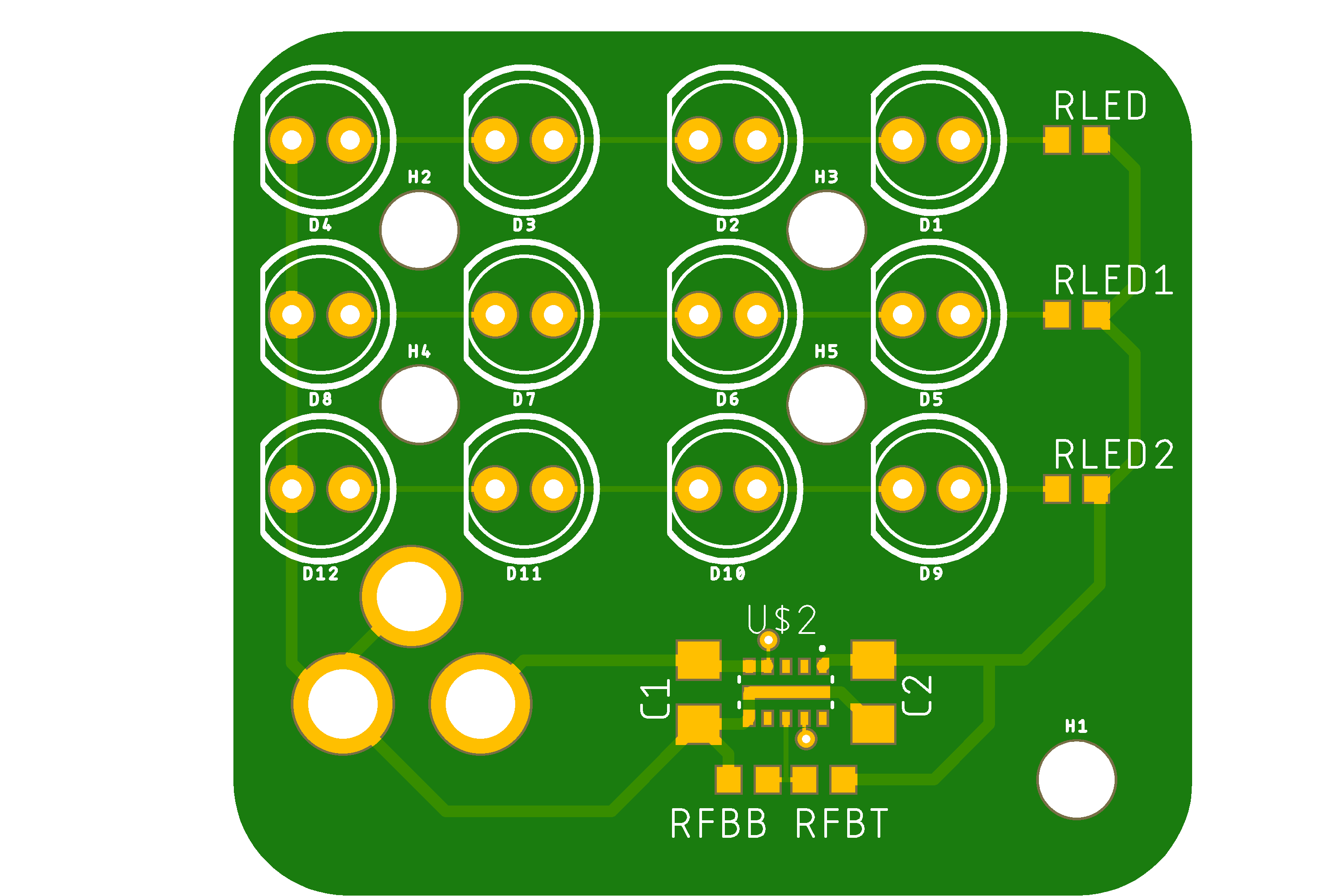
Fabrication
I ordered PCBs + Stencils on PCBway which arrived in under a week of ordering them and I prepared all the components and did a PCB reflow of the SMD components. The reflow oven at the hackspace is amazing!
I tested the DC-DC converter module using the bench power supply. Used alligator clips to supply voltage to the board using the through holes for the barrel jack, and measured the voltage at the output.
To my utter surprise, the output voltage was maintained at 15V even when I modulated the range of the input voltage.
I then soldered on the Barrel Jack and all the LED’s.
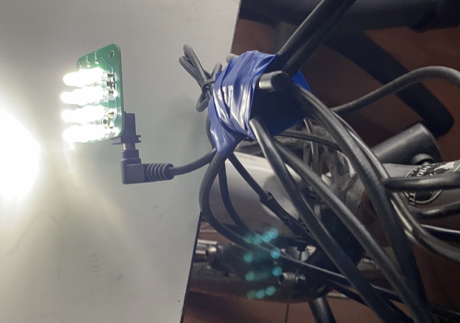
This is how it looks
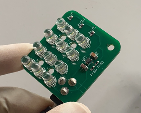
Since my bike was nearby, I plugged it in and voila! It is very bright.
Pls. stay tuned for the resin potting and lens write-ups ![]()
Any feedback?