Dustie's Tensioned Belts!

After a long time using belts that were falling apart, literally, from using a tensioning method which had a side effect of destroying the belt it was tensioning, the X axis finally split.

Search, order, wait, rethink, design, print, squirrel, forget, return, dang, redesign, again, pop, fizz, bang, bang, finally…

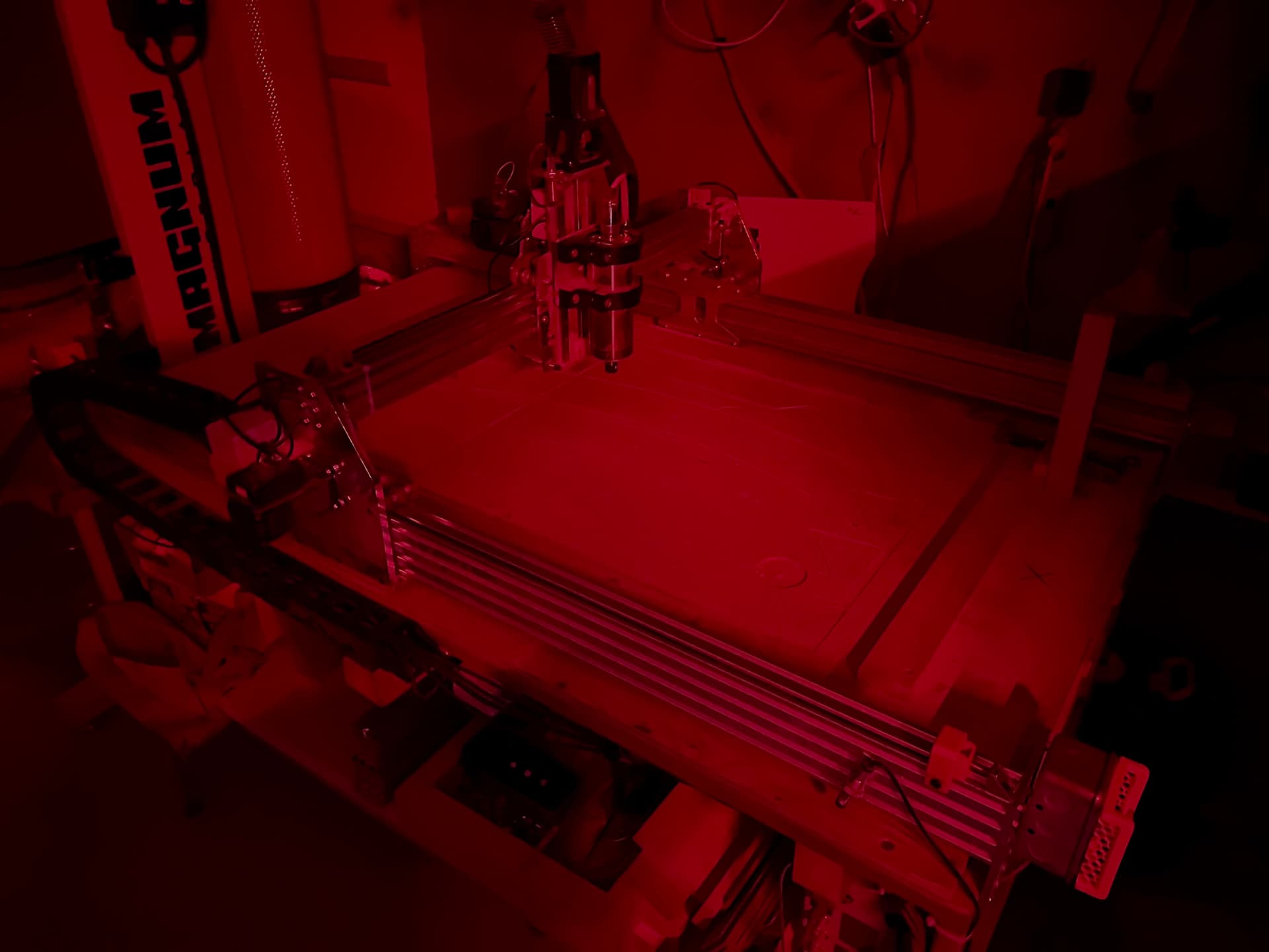
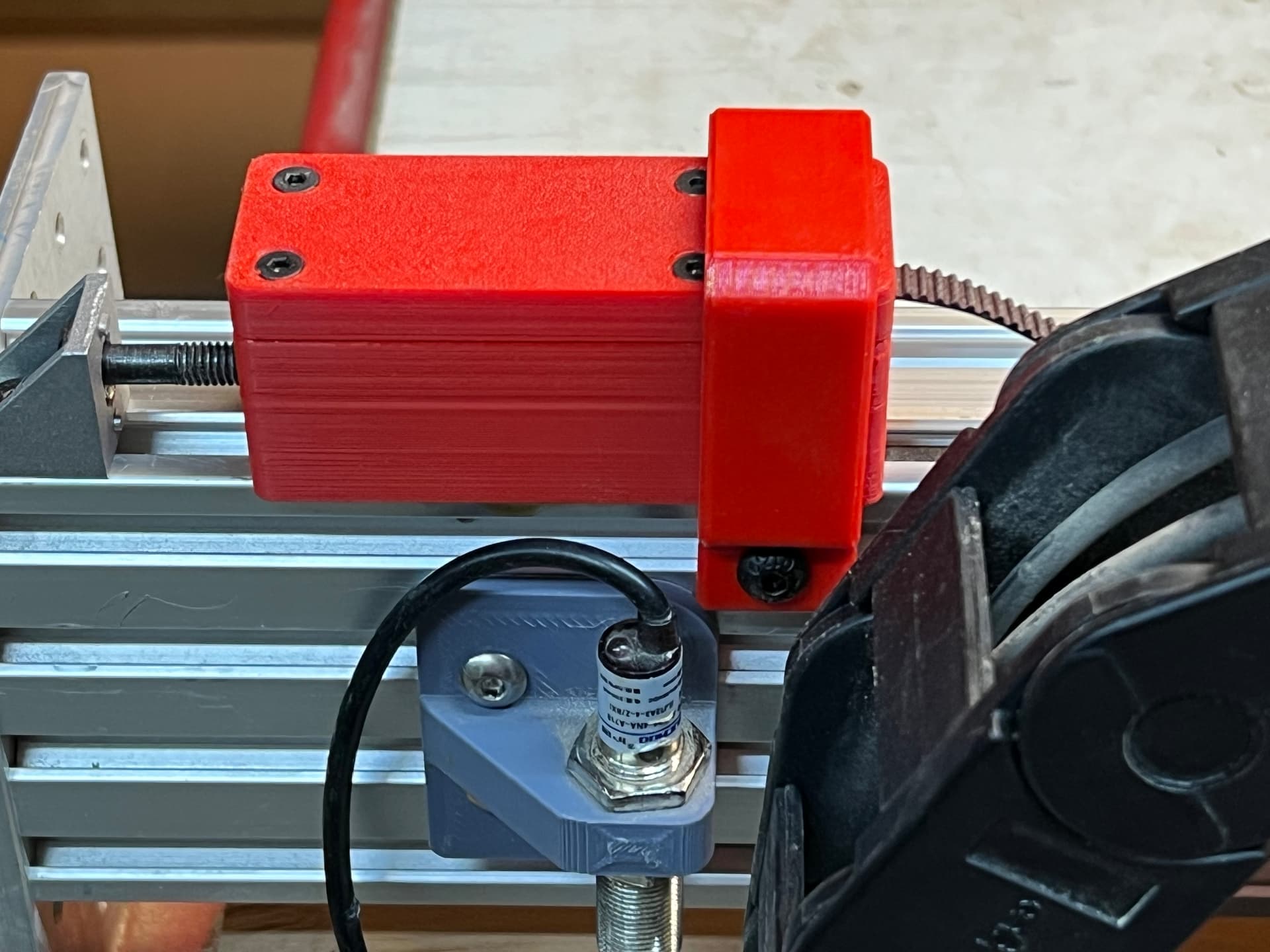
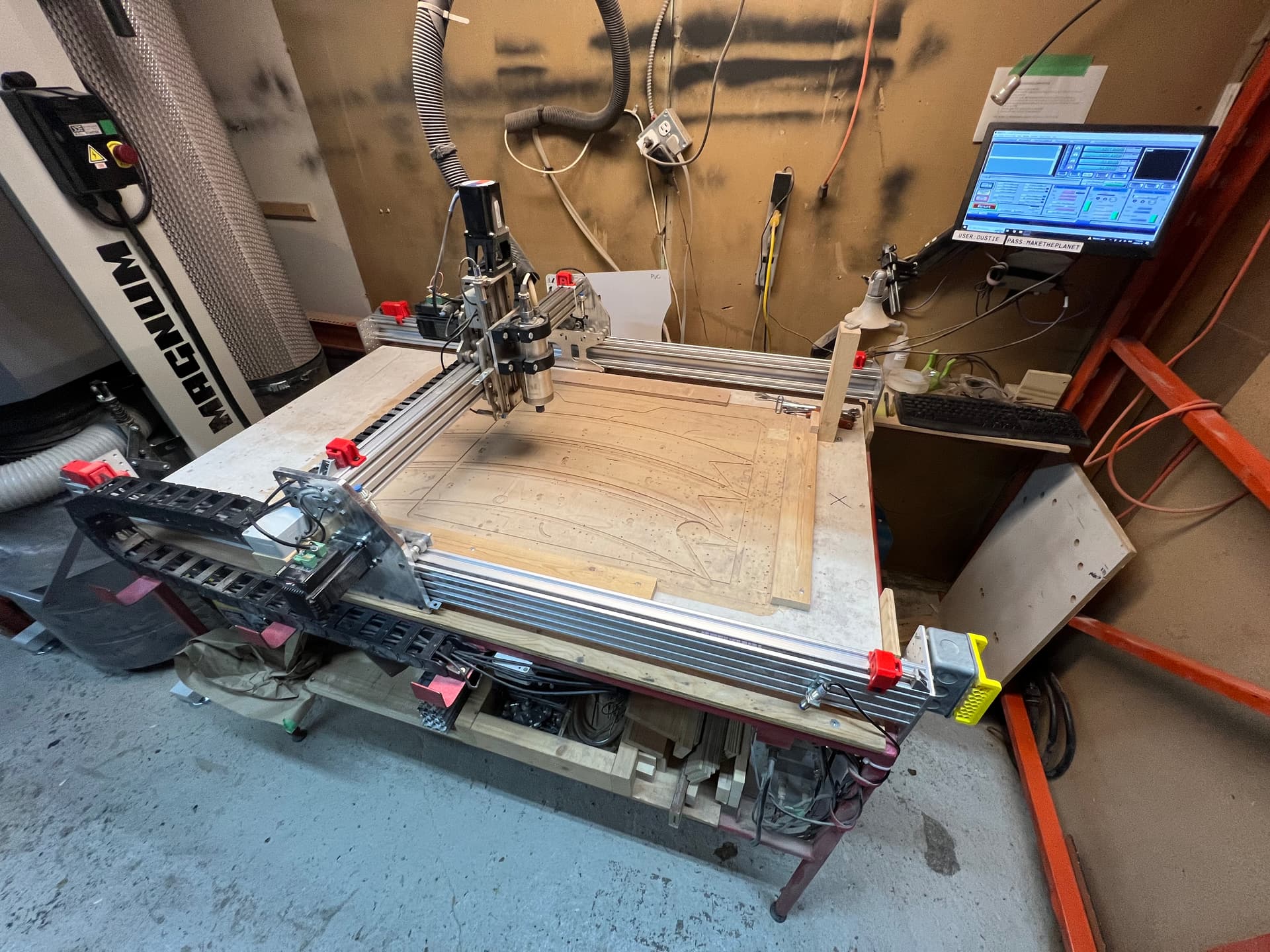
Dustie now has a belt tensioning system! And it’s easy to use and easy to print in vibrant red PETG. I’ll post the design to the wiki tomorrow. For tonight, highlights.

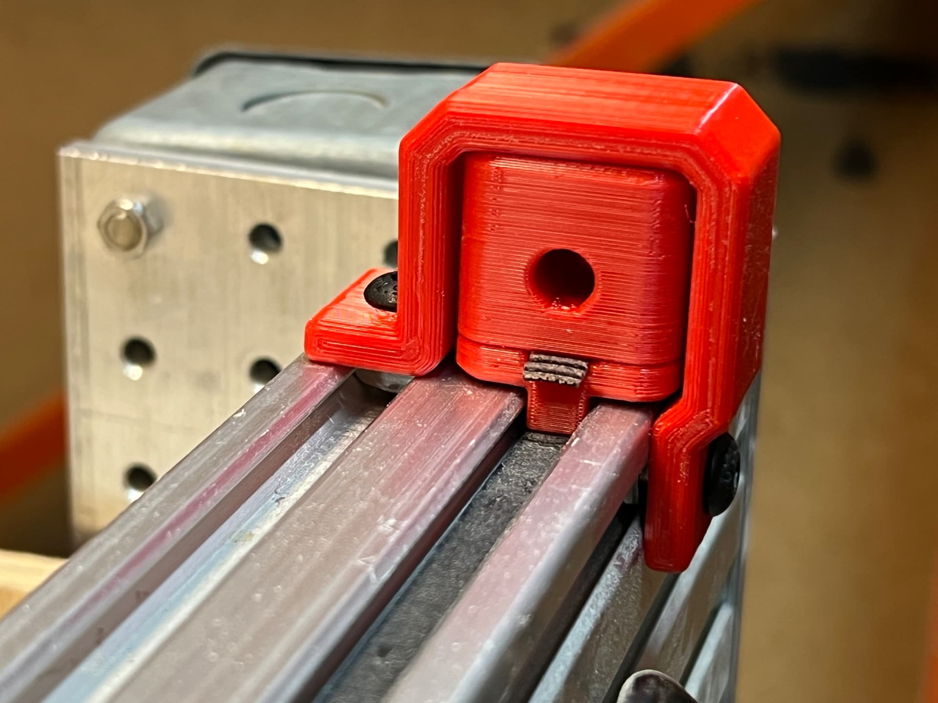
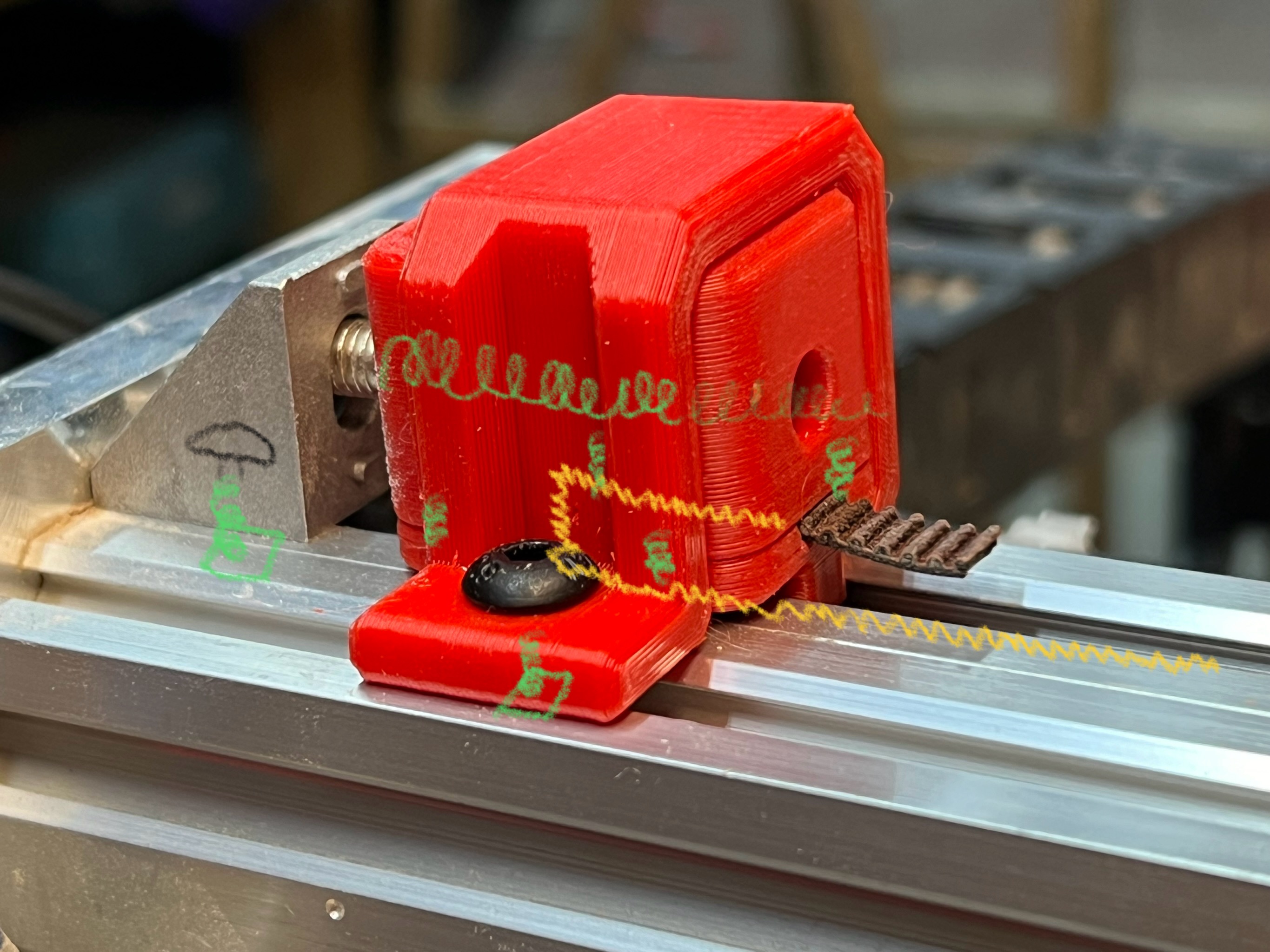
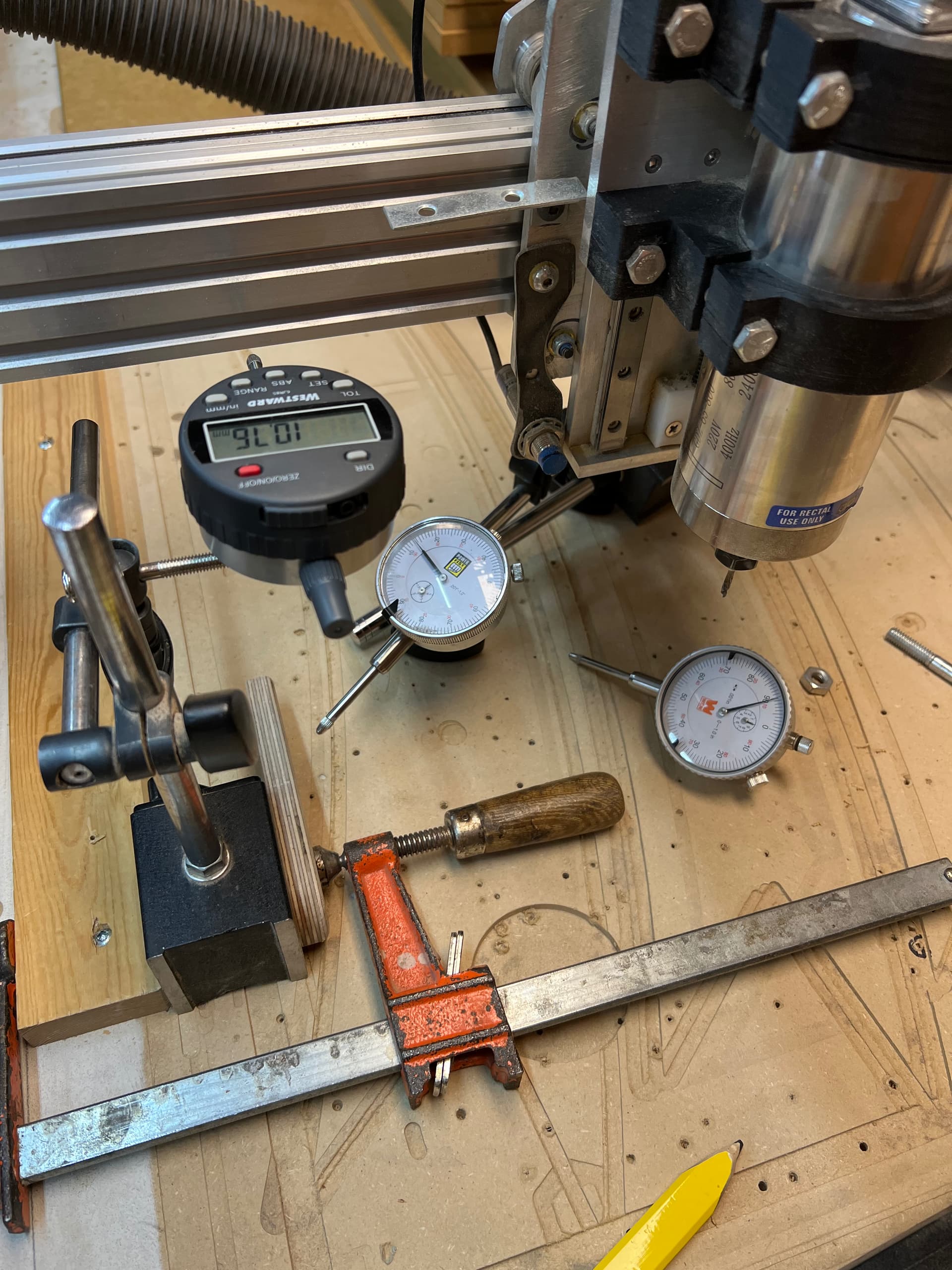
Designed in stages, and so thereby becoming a tad Frankenstein’s Monster in the process, there are two types of tension assemblies. They basically work the same, but one’s too big so most of them were retired and succeeded by these wee nimbles. The belt goes in the bottom, loops up through a channel with matching teeth, then clamped with teeny inserts 'n screws. A game of tug of war exists perpetually between the two buffers at each end of the tracks, assisted by the heft of a few M6 bolts. These are the heavy lifters of the system, unlike the red strapping, printed with an optimal orientation for its job and shape, acting like a tunnel lower mainland overpass for the otherwise skybound clamp. Someone more knowledgeable than me is welcome to make required adjustments to measured tension or stepper calibration, etc., and to invite me to witness.

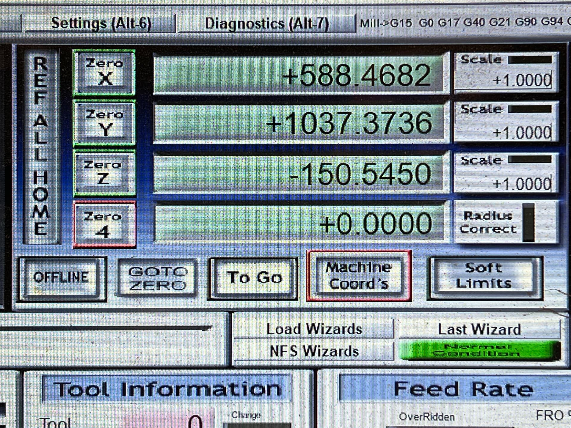
And the belts they’re holding? Fully certified fresh imitation knockoff factory ‘extras’ AliMcGates they’re pretty hey look over there! But being fixed, and fresh, and able to be as long as they need to be, Dustie’s theoretical maximums have increased pleasantly in two dimensions. It may be beneficial overall, including thinking of a modular bed system with integrated clamping instead. Bed rework will be required to use all the new space, and I may or may not undertake that.

While I was in there, I:

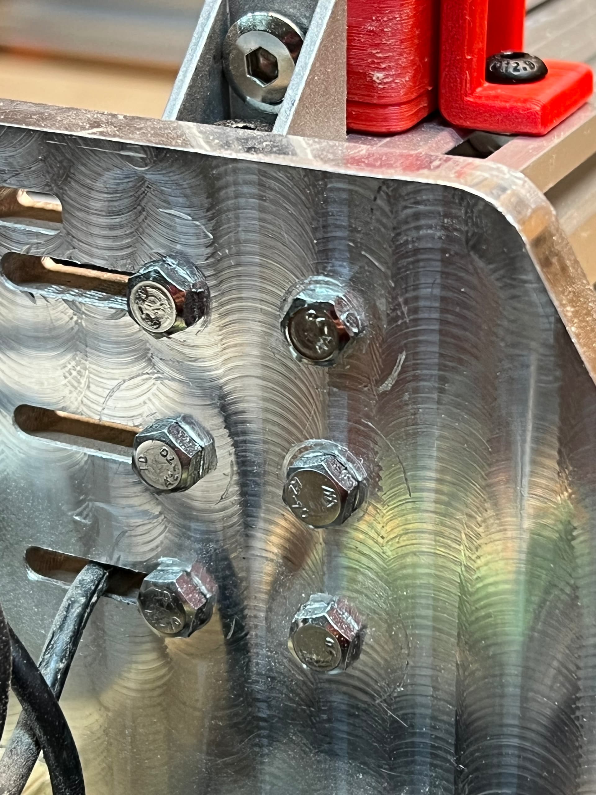
  • unified the entire frame bolts on a standard, easy to install, and fit for purpose length of bolt. Some old bolts were engaged by as little as one revolution. This is better.

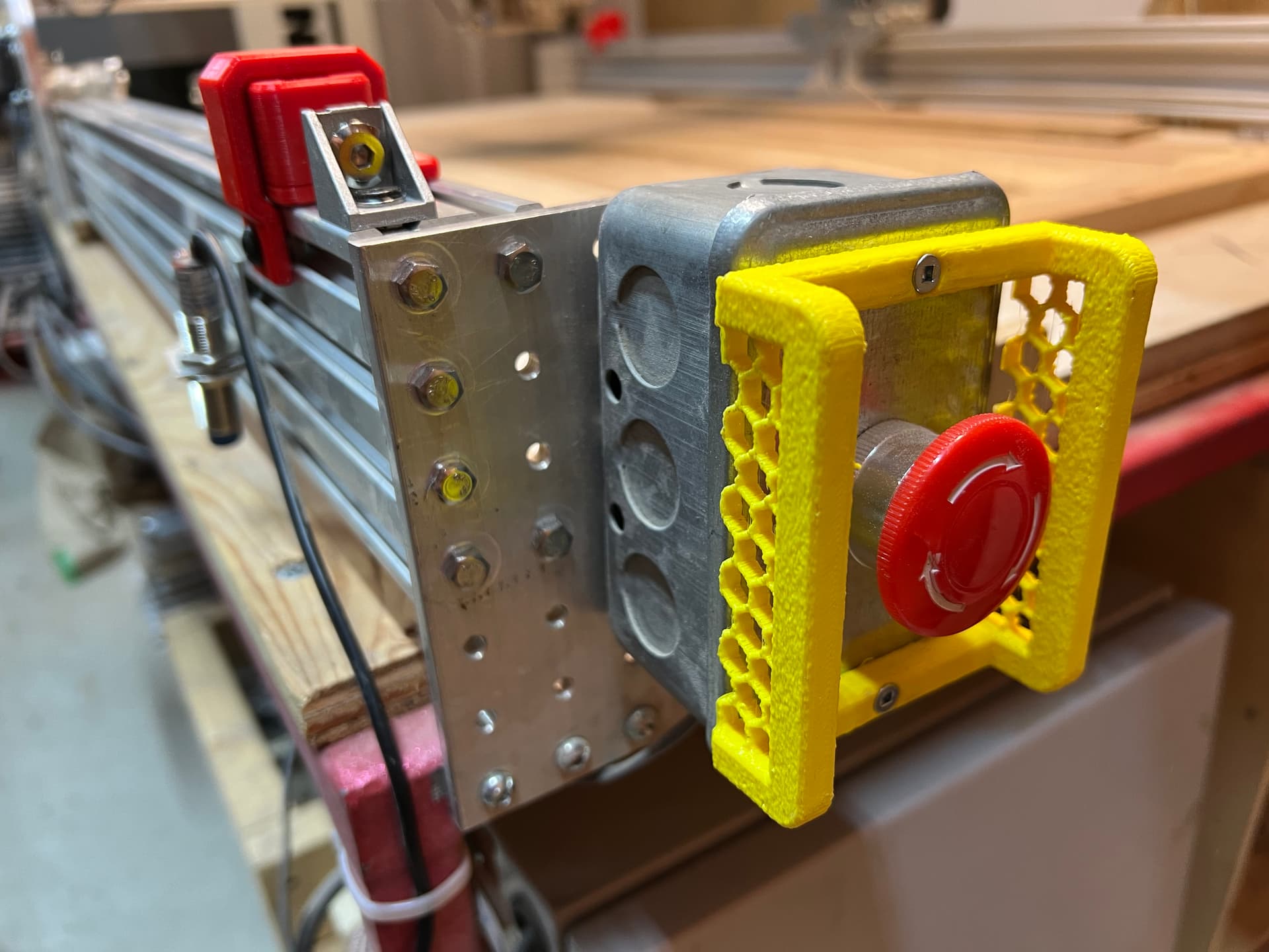
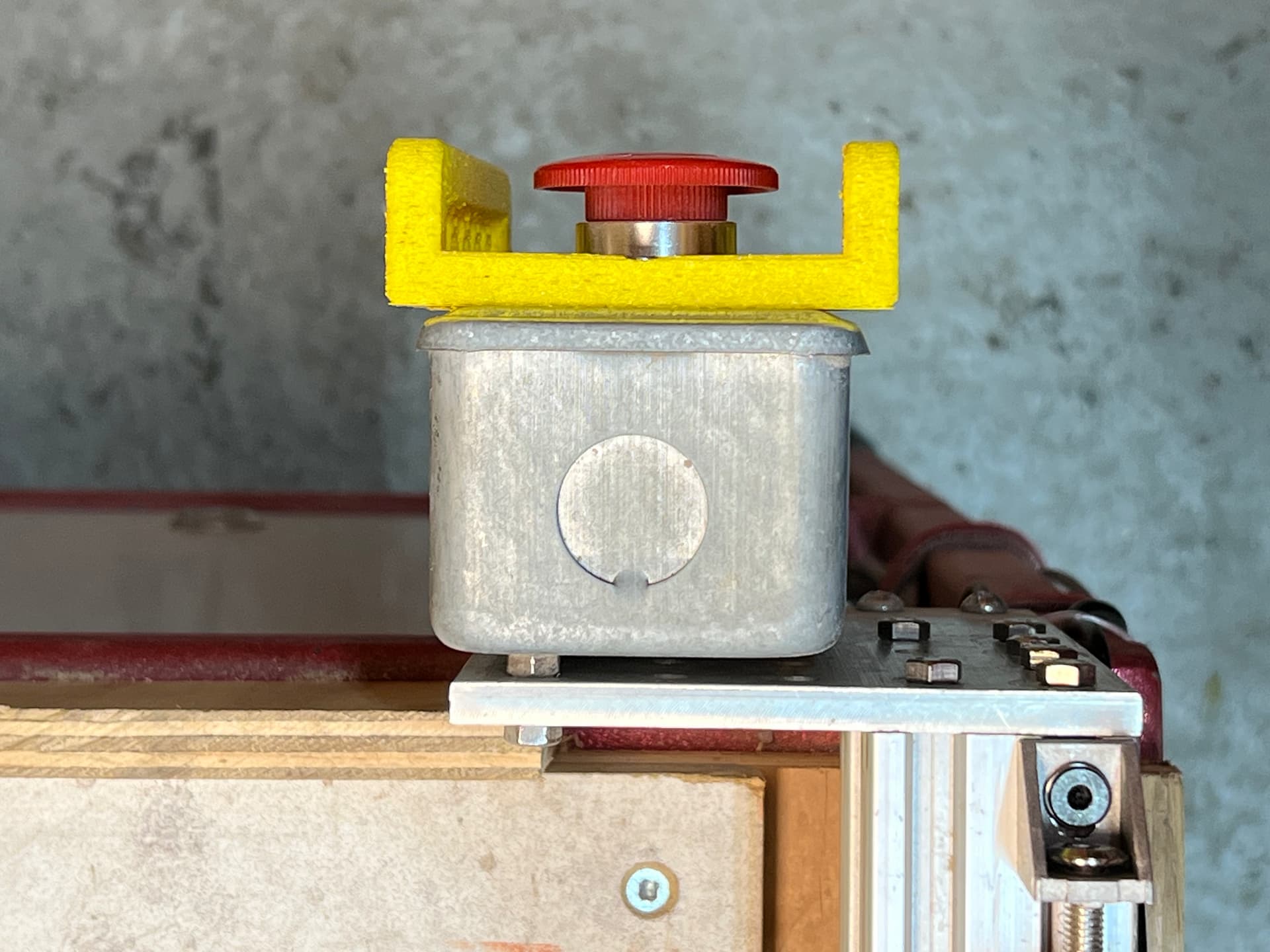
  • installed a low profile guard on the e-stop. I bumped this switch countless times which leads to increased stress. In a wood shop. Constructive discussion welcome.


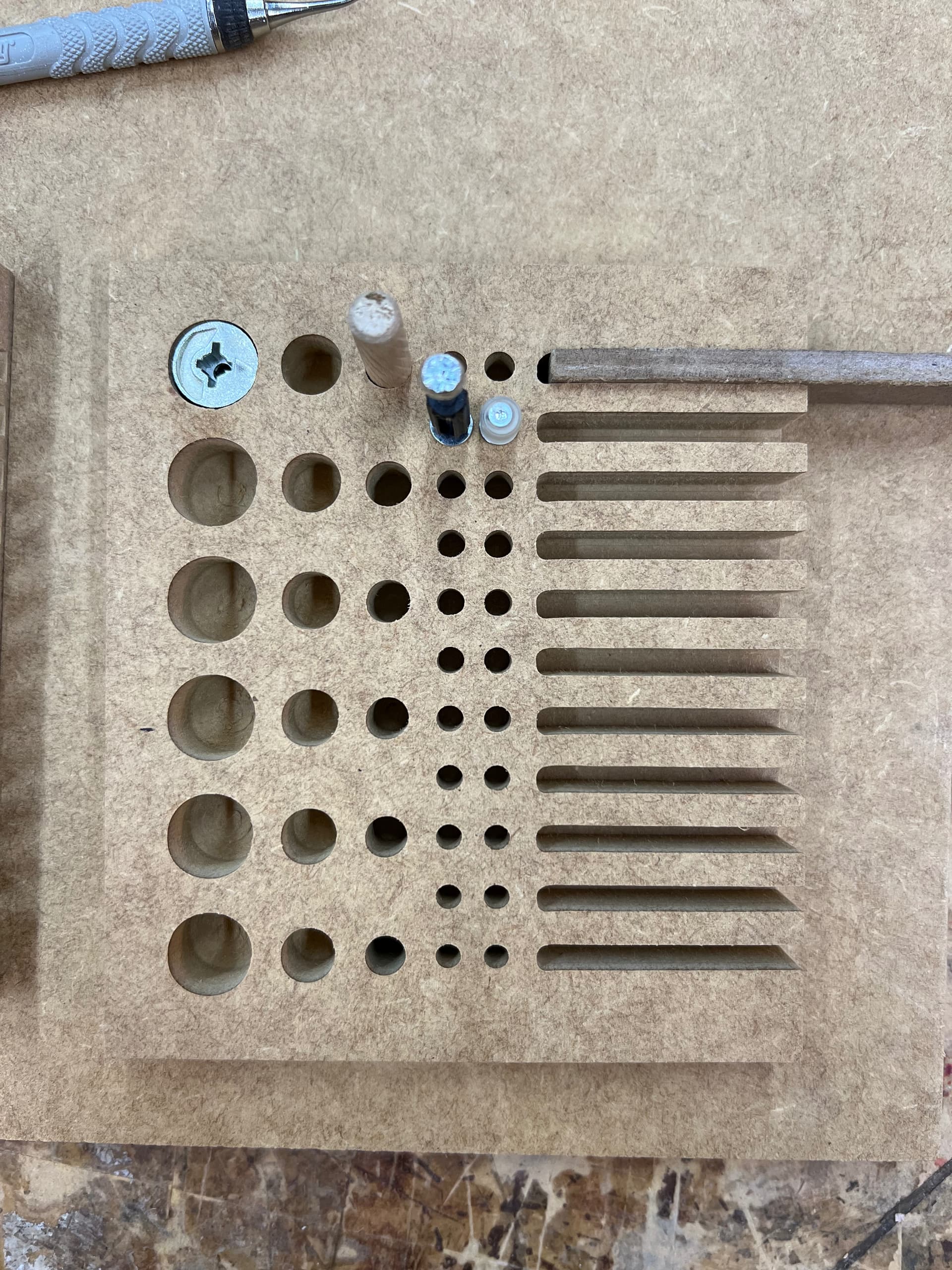
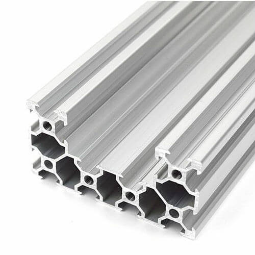
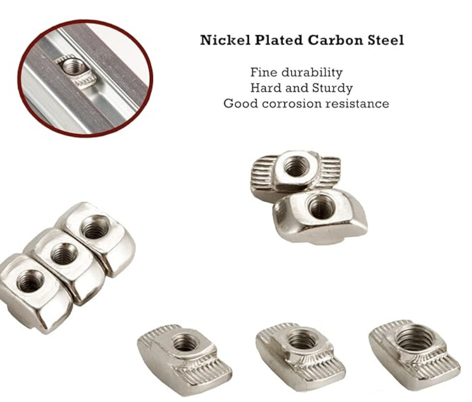
  • replaced the awful and bendy and tear-y and not side insertable rail nuts with these beautiful t nuts. All is good and right in the world now.

So that’s the story of Dustie’s new belts. May long they live.

Until then, goodnight.

6 Likes

The internals:

5 Likes

That looks awesome!

Thank you for improving Dustie!

That is amazing @Imagesurgery. Thanks for improving the space!!!

Yes, awesome. Thanks for keeping it going.

So the holes were still a bit eccentric after the re-belting. So out came the dial meters, and the vague memory of @AndroidLx poking at numbers and wee hidden buttons in Mach3 that allowed measurements to actually work. Top tip: I could only figure out how to measure in metric, despite it stating that non-metric measurements can be used. So if in doubt, measure with metric </life tips>.

But a dial meter on a janky CNC, I couldn’t get to the same hundredth of a mm more than… well, let’s, wait, what about backlash? Yeah. Got a bunch of measurements, with consistent gcode movements to either retain or remove the backlash, spreadsheets, averaging, etc. … so I did it all! We’ve now got measured backlash and measured front-no-lash and circles are more like circles and the numbers were heartwarmingly consistent between most measurements. Happy days!

Intended sizes still are off by a margin, but it’s consistent, mostly, so these are the breaks. The thing seems to be working, overall, in a very happy way and I’ll continue to learn what I can to make it even better. Until we just rip the thing out and put some happy ball screw monstrosity in its place :wink:

Enjoy!

10mm move Fwd X Fwd Y Backlash X Backlash Y
Average 9.9610 9.8795 0.1215 0.0485
4 Likes

Another update, this time to immortalise some ideas from @Hekseskudd and update the status of those interventions.

With the machine on, can you wiggle any part, or all the parts. You want as little wiggle as possible. It is likely caused by both mechanical slop as well as some control or power transfer issues.
I haven’t measured this, but yes. Some printed parts need actual fixing (z stepper mount), otherwise it’s just sloppy overall and I don’t know where it can be made more rigid (but I will look more closely and see what’s what, also if others have inspected and have ideas I am more than willing to brainstorm/workshop a solution/improvement!)

Also check if the control software is holding axis that are not active. My fluidNC system was set to default as not holding. This caused me all sorts of unnecessary grief.

Will check. The machine is held whilst on, and inactive, so I don’t know if that’s a separate state or not. I believe it is held because I have been shown how to minimise backlash physically by holding on to one axis, with firm and consistent but not too much pressure. It’s a real pain so I don’t really do that.

Measure the frame diagonally and/ or do test cuts of circles and squares. See how parallelogram or oval they are.

I have done this for small circles (5-15mm), and they were terribly eccentric but have become improved with the tensioning and adding in measured backlash values. However, I believe further testing is necessary and I am seeking a method for this (I’m currently at ‘just make stuff certain sizes’ but believe there must be more of an ‘NTSC test pattern’ type solution which is more generalised and actually captures the required data cleanly/reliably)

How much backlash is in the system? How much deflection can you introduce axially with your hand.

Backlash is minimal, I can reliably measure X:0.1215mm Y:0.0485mm; I’ve not measured Z as my current needs are 2.5D only, but I will need to test this too. Z might be utterly terrible given the failed stepper mount. Deflection by hand is also terrible and as alluded to above, I have not measured it nor do I know how to deal with it directly/properly.

Not familiar with Mach 3 but does it have a small circle minimum setting, or are your vectors made from arcs or a truncated representation?

I’m using G3/G4 commands for sure, and have taken steps to reduce the size of my code in CAM (F360, mostly by ensuring that tolerance is not too high and smoothing is either on or set to arc fitting, depending on operation). It’s at a point where I do not notice stuttering any longer, as a matter of course. It used to be bad but that was before I reduced accuracy a touch (it’s still very accurate, just not silly accurate).

Is the Y gantry captured by the x axis rails or can it lift off?

It’s captive rollers mounted on machined aluminium plates, at least 8mm or so, top and bottom of some 8020 C-profile extrusion. Seems fairly robust, overall, but still might have improvements (the rollers do not appear tuneable, for example)

And this one sounds stupid but it’s the cause of a lot of problems: are the pulleys on the motor shafts keyed/gripped/not slipping?

The belts are Gates 2GT-6mm, and the motors all have pulleys with what appears to be matching teeth. Motion testing (using gcode for repeated movements, removing backlash by overshooting and returning if necessary) reveals very reliable, repeatable results in the 10mm movement range with no load, but I’d love to test this over longer distances but am not sure how, exactly, to scale this up to the whole machine or thereabouts.

2 Likes