Background
I have converted my 2002 VW mk4 jetta 1.8t to run bi-fuel on CNG. I have free access to CNG at work so this makes running the car much cheaper.
To take advantage of the higher octane rating of the fuel (130+) and to make up for lost O2 due to displacement in the air intake (CNG is injected in the intake port as a gas, not liquid like petrol), I would like to run more turbo boost.
What i’d like to do is run two levels of boost, one for 93 octance (~15 psi) and a second level for CNG at approximately 20 psi. The car determines fueling based an a MAF reading, so I can pretty much increase boost to safely 20psi without causing any engine issues
Project Goals
- Dual stage electronic boost controller
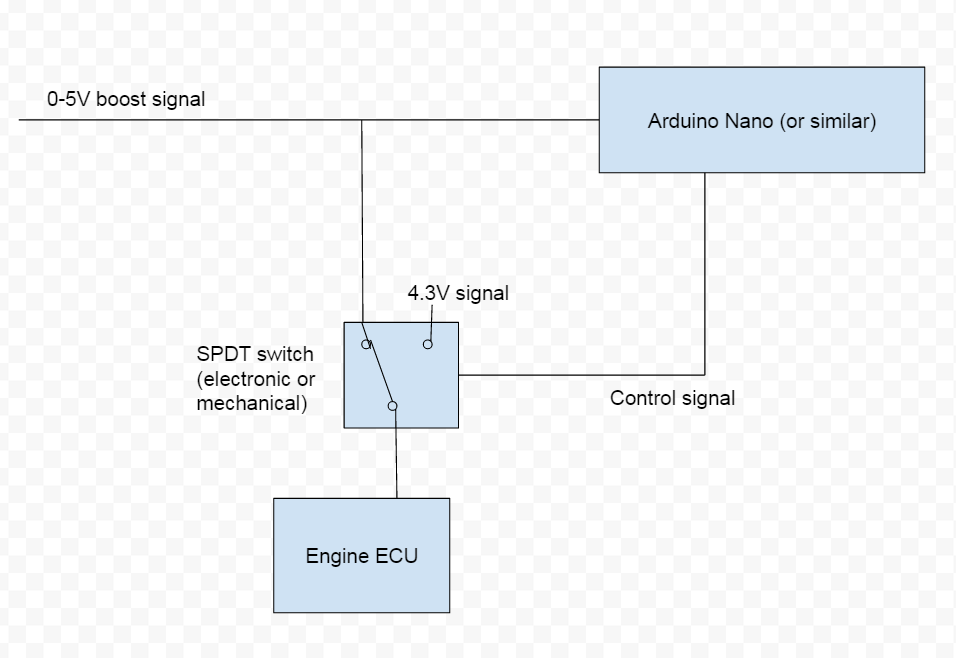
- Boost pressure sensor (0-5V) signal to be capped at 4.3V to the ECU
===============================================================
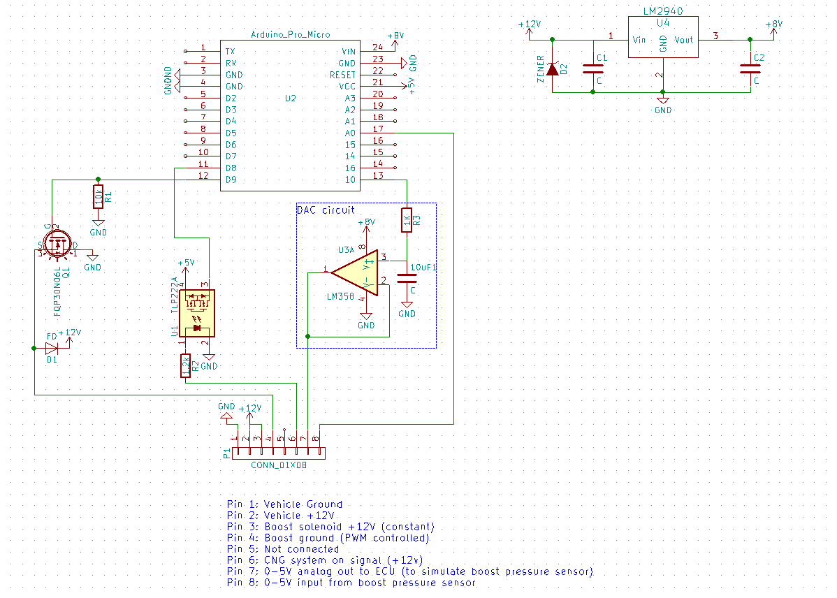
Dual stage electronic boost controller
- Arduino nano or similar microcontroller
- PWM the stock solenoid valve (N75 valve) to regulate wastegaste pressure and thus control boost
- PWM frequency to be approximately 20 Hz
- Drive the solenoid valve with a MOSFET transistor (with appropriate flyback diode)
- Inputs will be: boost pressure transducer (0-5v input) as well as a 5V digital input from the CNG controller to say that the system is in CNG mode.
- Logic will read boost transducer voltage and then lookup the desired PWM in one of 2 tables (gasoline mode or CNG mode).
Current questions on boost controller:
- The N75 valve has a resistance of 30 ohms (2.5 amps current draw) and needs to cycle at 20 Hz. Can anyone recommend an appropriate MOSFET and flyback diode to drive the valve?
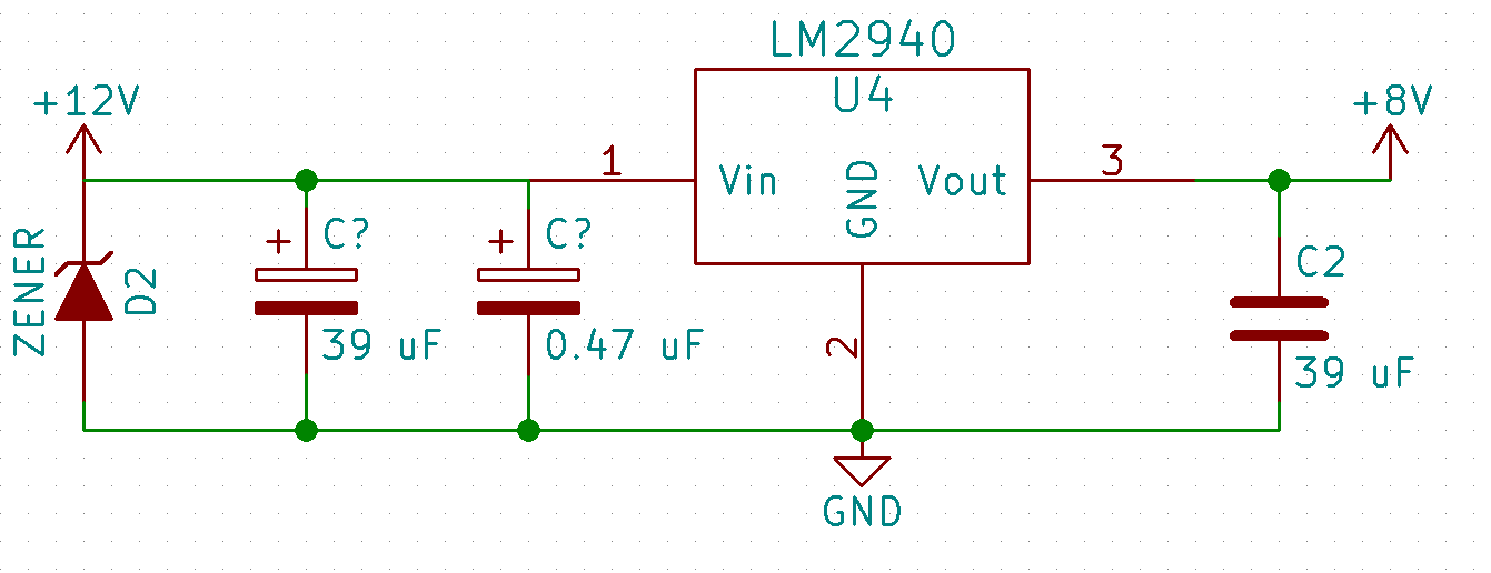
- Can anyone recommend a strategy for filtering the power supply to the controller to keep voltage spikes from the solenoid valve from resetting the controller? I presume the flyback diode will help, but do I need to add any additional RC snubbers, MOV’s etc…
===============================================================
Boost pressure sensor capped at 4.3V to the main ECU
The purpose of this mod is to prevent the stock ECU from seeing more than 11 psi of turbo boost. This is the stock boost reading and therefore the ECU wont sense a problem enter limp mode. Because the ECU determines fueling based on a MAF (mass airflow reading) and O2 sensor feedback, fuelling should be taken care of.
Common solutions to this problem is to install a 4.3V zener diode on the signal line of the pressure sensor. This will dump any voltage over 4.3 volts to ground and prevent the ECU from seeing a value higher than this. The problem I have with this, is that I want to actually read the real signal on the electronic boost controller above, but have the ECU only see 4.3V.
Needs
- Read the 0-5V output of the pressure sensor unmodified at the electronic boost controller
- Cap the voltage fed to the ECU at 4.3V
Questions
- Can someone suggest a circuit to handle this?
- Would a circuit like below make sense? Anyone suggest a mechanical or solid-state SPDT switch?
Thanks for the help everyone
Here is a photo of the car on its first CNG fill