tl;dnr - I made a fidget spinner. See my Youtube Fidget Spinner video.
Slightly longer version ![]()
I recently saw some Youtube videos of various fidget spinners and spinner builds.
I liked them and figured this would be a great project for the VHS Taig CNC mill.
Started off with a 3D design in Autodesk Fusion 360. Worked out some CAM paths and then cut the top and bottom part out of aluminum bar stock.
Some pics below.
The top and bottom are mirror images so only one set of CAM files were required for milling.
Top and bottom parts of fidget spinner with a standard Roller Blade bearing.
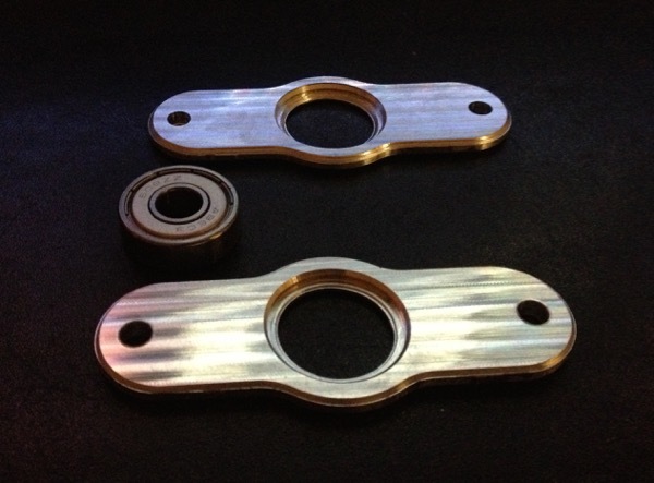
Bearing seated inside bottom face
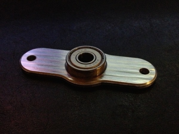
Top face placed on top of bearing.
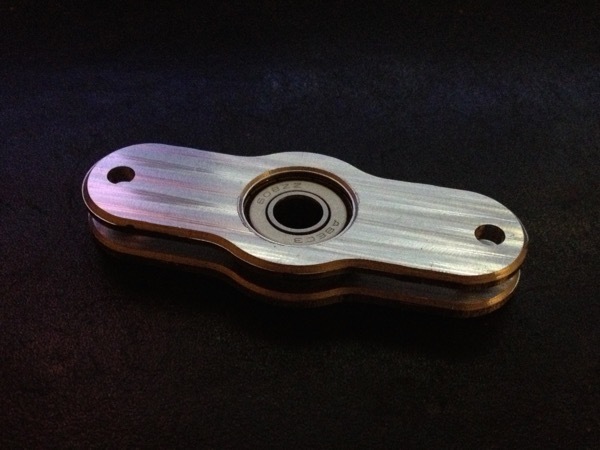
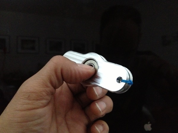
The two faces just wired together because I want to see if this thing spins.
The original plan was to use acorn nuts with threaded rod but to costly and raises the profile too much.
To see it in action
Check out my Youtube Fidget Spinner video.
The following gif is misleading as there there are actually 4 separate spins happening and photographing something spinning makes it look like it is spinning much faster than it actually is.
