It was great to meet and see your projects during the culture crawl. Martin and Phillip were very generous in showing me the space and more. They even provided their own tools for my start-up project.
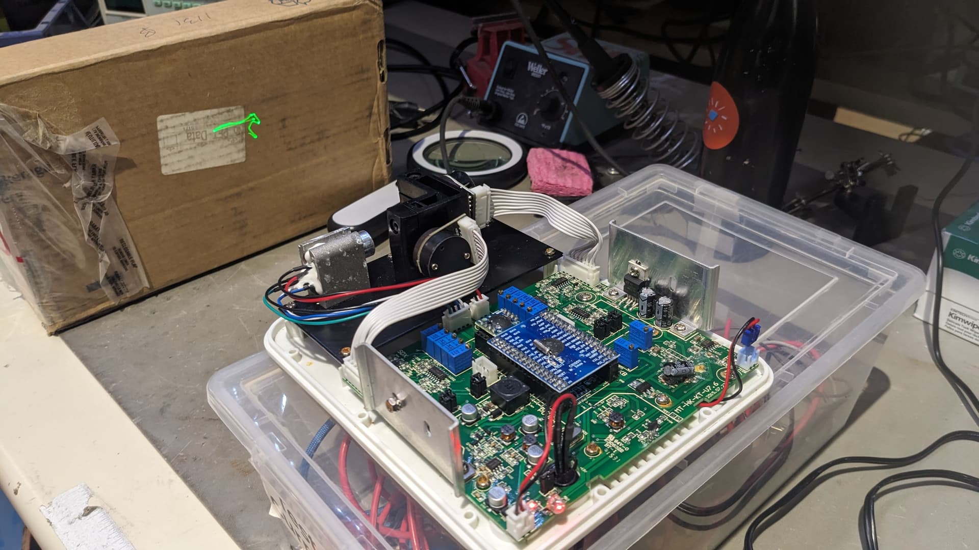
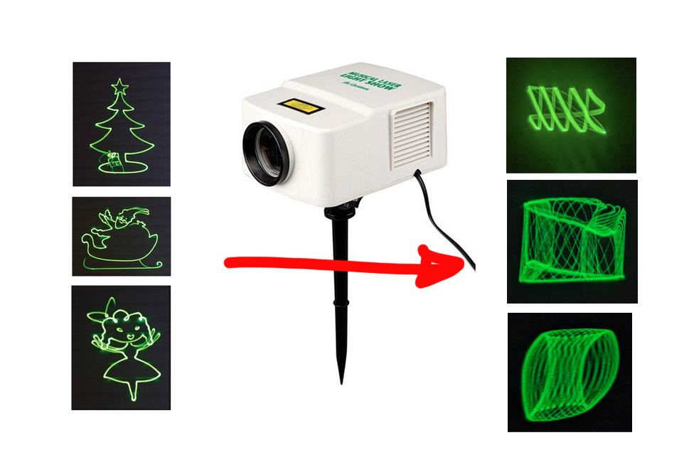
Recently, I came across a broken Laser Projector by Mr. Christmas at a thrift store, and now I’m looking for a way to customize it. The other night, I wiggled around and managed to turn it on. It’s a basic laser projector with X/Y ‘galvo’ mirrors that reflect beam to draw Christmas/Halloween themed images. I want to send custom drawings, and one way I thought of is by sending voltage for the X/Y motor. However, I’m afraid that doing so might fry the board. I’ve been searching online for the board’s datasheet without any luck. Is there anyone familiar with electronics and motor control who can help guide me on possible ways to accomplish this?
This looks really challenging, but like, challenging in a fun way.
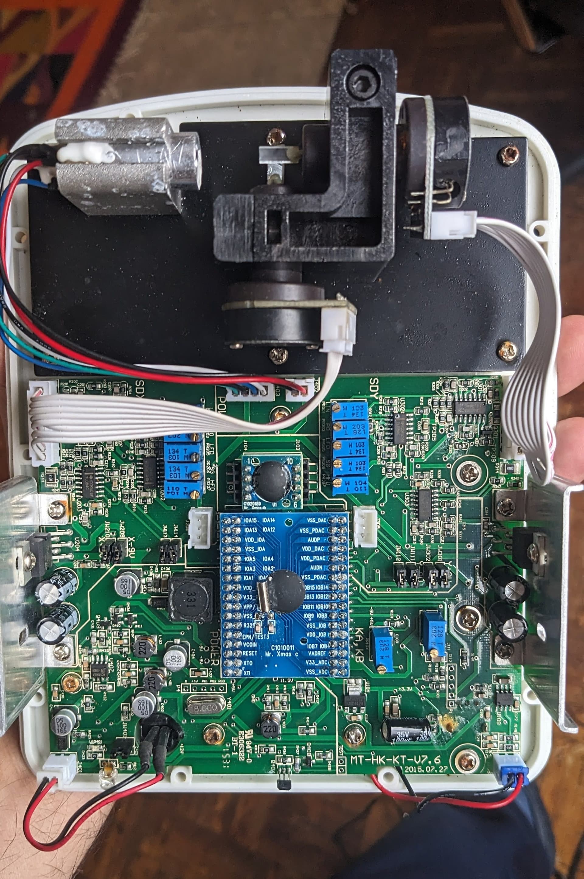
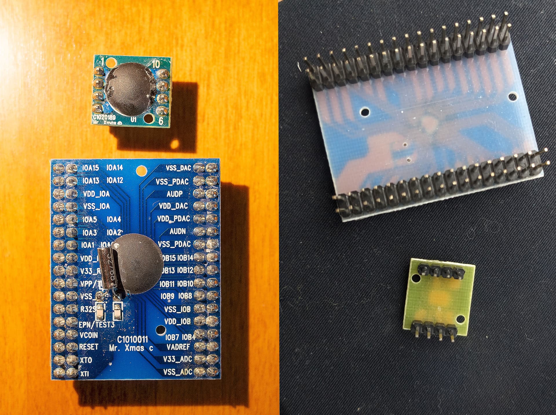
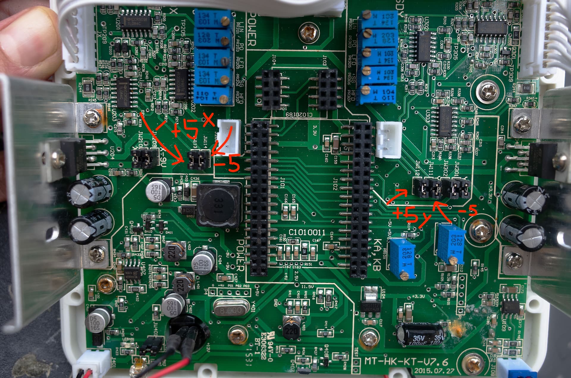
It looks like this is a generic OEM board, and different manufacturers can supply their own daughterboard - The blue ones by Mr. Christmas, in this case.
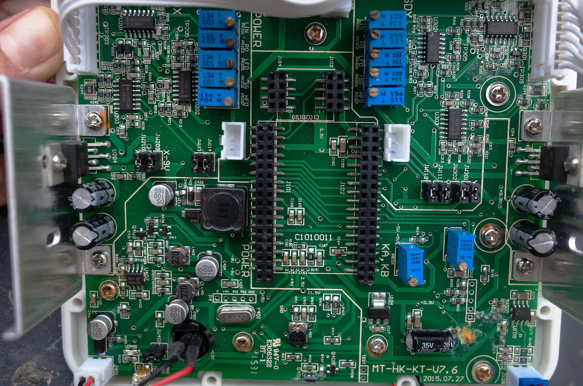
Can you pull off the two blue PCBs and take another picture? They are just square header pins, so they should be removable with just a little bit of force, no desoldering necessary.
I think the end-goal would be to make your own PCB to replace those, with your own microcontroller.
Thanks Marcus! I appreciate your link and concern. I am actively taking precautions while working at VHS to ensure safety. Specifically, I am adhering to safety regulations by keeping the beam intensity below 5 milliwatts and keeping it always pointed to the wall. I will also inform those around me about the nature of my work to ensure their safety as well.
Thanks Jarrett for jumping in on this one! Attached photos below.
Projector continues to function properly even without the small PCB. When I remove the large PCB, it remains in the neutral position indicated by a green dot.
Desired goal is to control X/Y motors either through a microcontroller to send real-time coordinates or by utilizing a DAC to send voltage directly (if possible).
We chatted briefly when you showed me this project on Monday. Either of the options you’ve suggested (DAC or microcontroller with a DAC) are great approaches to the problem. I might suggest using a standalone DAC (if you already have it) for initial testing just to make it simpler.
Do you have experience using an oscilloscope? That is going to be the best tool for finding out where to inject a signal, and what kind of voltage levels are safe.
As a very first guess, I would scope out the inputs (pin 1&2) of the TDA2030A chips on either side of the board (the ones attached to aluminum heatsinks).
I have a suspicion that these audio amplifier chips are used as power amplifiers to drive the galvanometer motors. Just a hunch that could be misguided or completely wrong though!
As an aside, I just searched for “galvanometer Lin po hfd” and it turned up this datasheet for a different generic galvanometer driver that explains what all those letters mean. Tl;Dr they are various tuning adjustments/feedback signals that you probably don’t want to mess with.
Let me know if you want help probing around with a scope some time!
Thank you for your response and suggestions! Currently, I am using a Raspberry Pi with a HiFiBerry DAC+ to draw vectors on an oscilloscope. However, I recently received a gift of the Motu Ultralite MK3, which can send balanced +/-5V signals. Since the ILDA protocol for controlling lasers uses the same voltage, I believe it could potentially work for this project as well, considering it is the same analog technology.
I attempted to inject the signal into JW210 and JW114 for the left channel and JW301 and JW112 for the right channel from the HiFiBerry DAC+. With this setup, I managed to get minimal motor reaction to sound, but it didn’t feel quite right. I suspect that the signal needs amplification. However, I didn’t go further in my testing due to concerns about potentially damaging the equipment.
I agree with your suggestion of scoping the board for another place to inject the signal. This would provide a more accurate understanding of where to inject and what voltage levels are safe. So far, my experience with an oscilloscope has been limited to drawing lines. I would love to learn more about using it properly. If you are available in the coming days, I would appreciate scoping it together.
I’m thrilled to share an update on Mr Christmas Laser Projector turning into Mr OpenBeamer. Not only can it now play Christmas-themed animations, but it can also display a variety of other animations (and sounds).
Using the sound modulation I’ve been able to control laser light in real-time to create complex animations. It is reverse engineering for purpose of taking the control of the system to make custom shapes to generate audiovisual works. This became a main goal of my current research.
Thanks to @ddq assistance with using a lab oscilloscope, we were able to trace the signal on the existing board. Our collaboration revealed that we were actually working with similar technologies in different domains. After our first meeting, I spent a sleepless night continuing the trace and finally managed to gain control over the system. The result ware complex Lissajous figures created using sound synthesis combining left and right channel:
It was nice to improvise bit what if I use software for creating a reproducible and more controlled library. With the software I manage to translate simple 3D forms directly into sound and then draw vector animations in real time:
This project has furthered my interest in controlled laser light and its potential uses in audiovisual performances. It also opened up possibilities for creating static light paintings. Here is another example where modulated laser light was synchronized with video from the same source:
This project has further motivated me to write a paper on Synesthesia, cross-modal phenomenon where stimulation of one sensory pathway leads to experiences in a second sensory pathway. Basically, what we see is what we hear. Signal that drive motors to reflect light beam is at the same time produce sound through speaker coil. Some of you may have heard about Jerobeam Fenderson’s ‘Oscilloscope Music’. In a similar principle as on oscilloscope in the Cartesian system, I am using sound source to modulate laser lights on X and Y coordinates and at the same time produce sound on the speaker system. Vancouver Hack Space and other open communities are playing significant roll in development of this projects and I want to thank to everyone who helped. Part of essay is acknowledging everyone for their collective effort that emphasizes the significance of do-cracy and an open approach we have at the VHS. A draft version of my essay is attached bellow. I plan on continuing scoping and documenting the board as the signal is still weak at these spots. If anyone else is interested in this field and wants to collaborate on this project, please let me know - we could jam together!