I’m coming to you to see if anyone has some basic wiring knowledge they could share with me.
I got an old arcade stick, expecting another collector’s item, but turns out the kid gutted the wiring and terminal strip inside. I got a deal as a result and kept it with the intent to either get it back in its original working order or just by a new PCB and make it universal stick. That is the easier thing to do, but I got it for a game on Wii and if I mod it, I’ll lose that compatibility. It’s a 10 year old product though so finding info is hard.
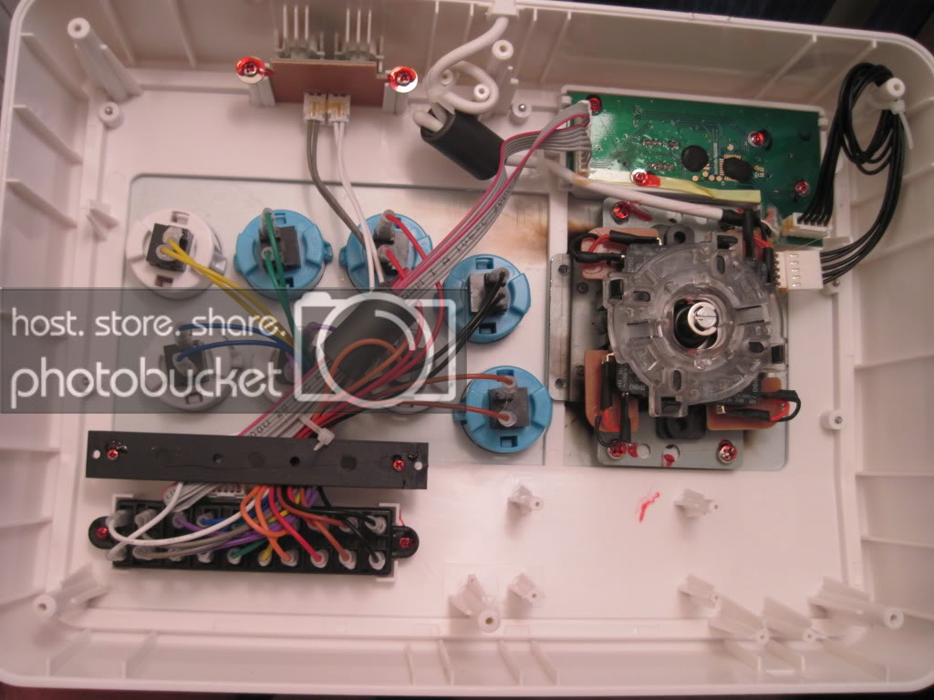
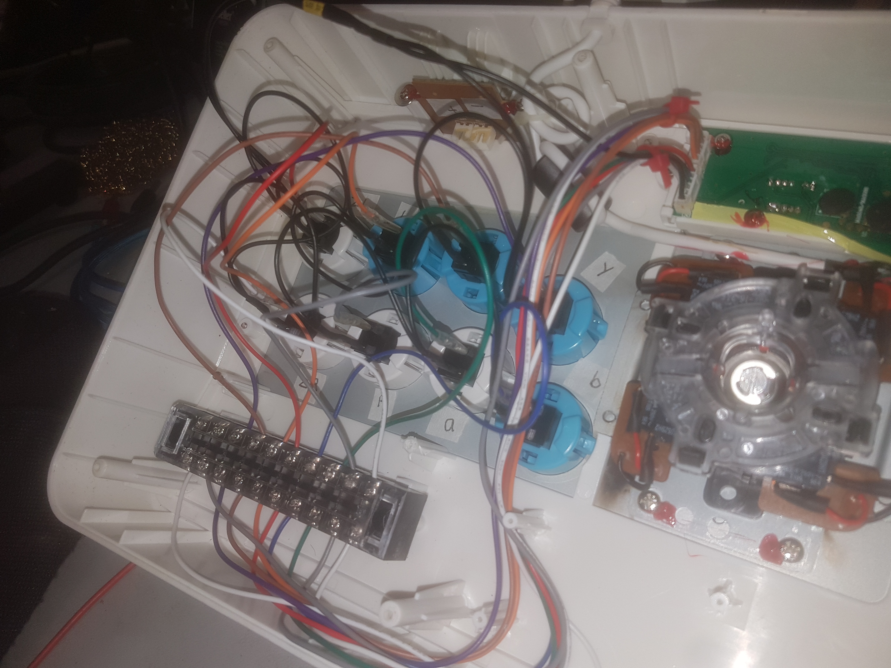
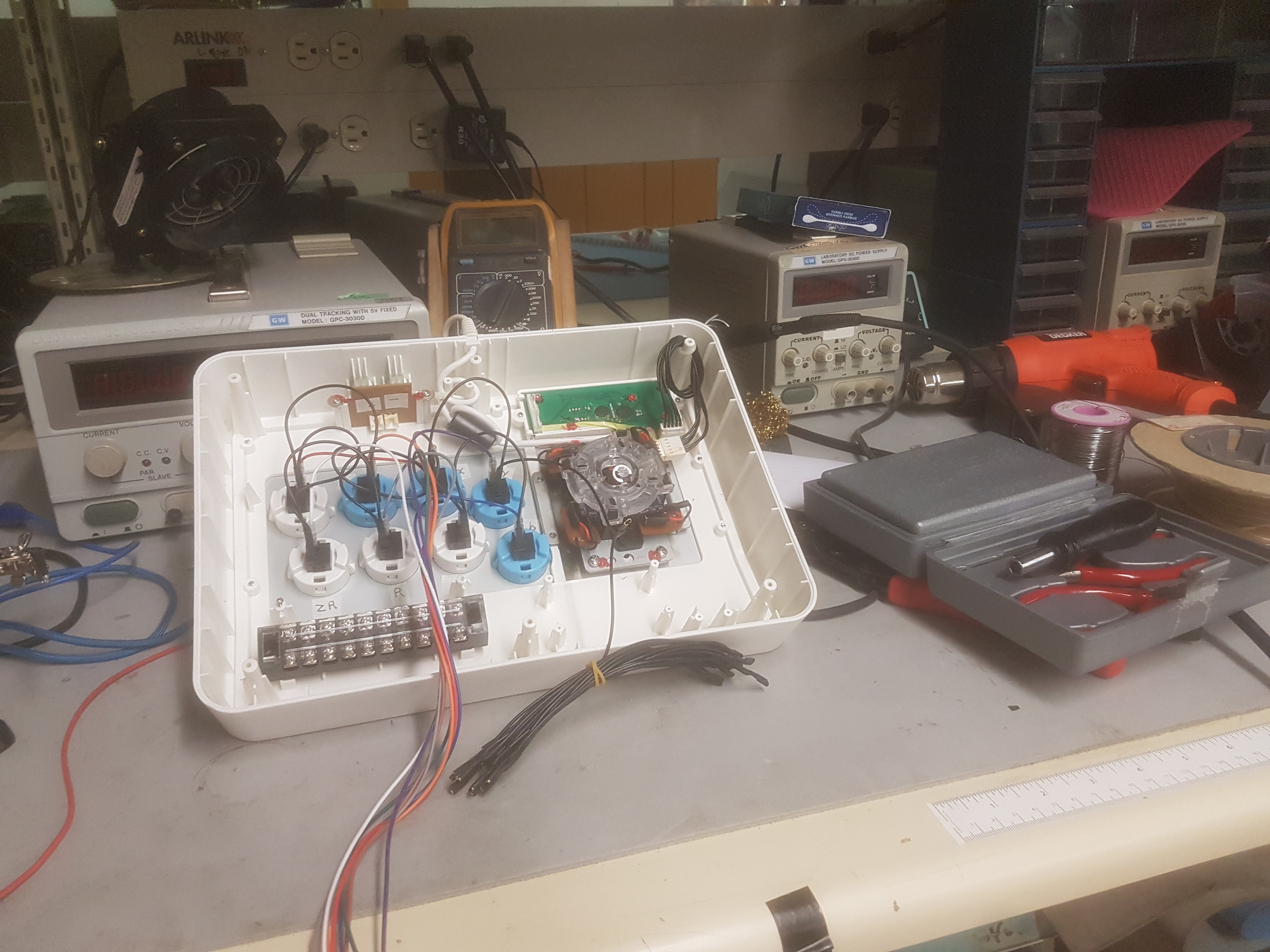
I’ve attached two images, one of my stick with what’s missing, and an image of the inside I found online. Buttons use .110 Quick Disconnect wires, and connect to a 10 pin terminal, but then it seems two 5pin and 6pin ribbon cables hook up to the terminal and then connect to the PCB. The company that made it was Madcatz and is out of business, but I’ve seen some images of similar terminal that have these extra connections soldered on. That said the total connections are 11 pins, so I wonder if it’s just straight up the 10 lines that just connect to the board from the terminal? If that’s the case, I could test this with a termial and the 5pin/6pin harnesses.
But yeah, in short, I’d like to talk to someone who may know about wiring these basic buttons in a way that works, or if I’m wasting my time. I could meet at an open house sometime if anyone wants to take a look at this thing.
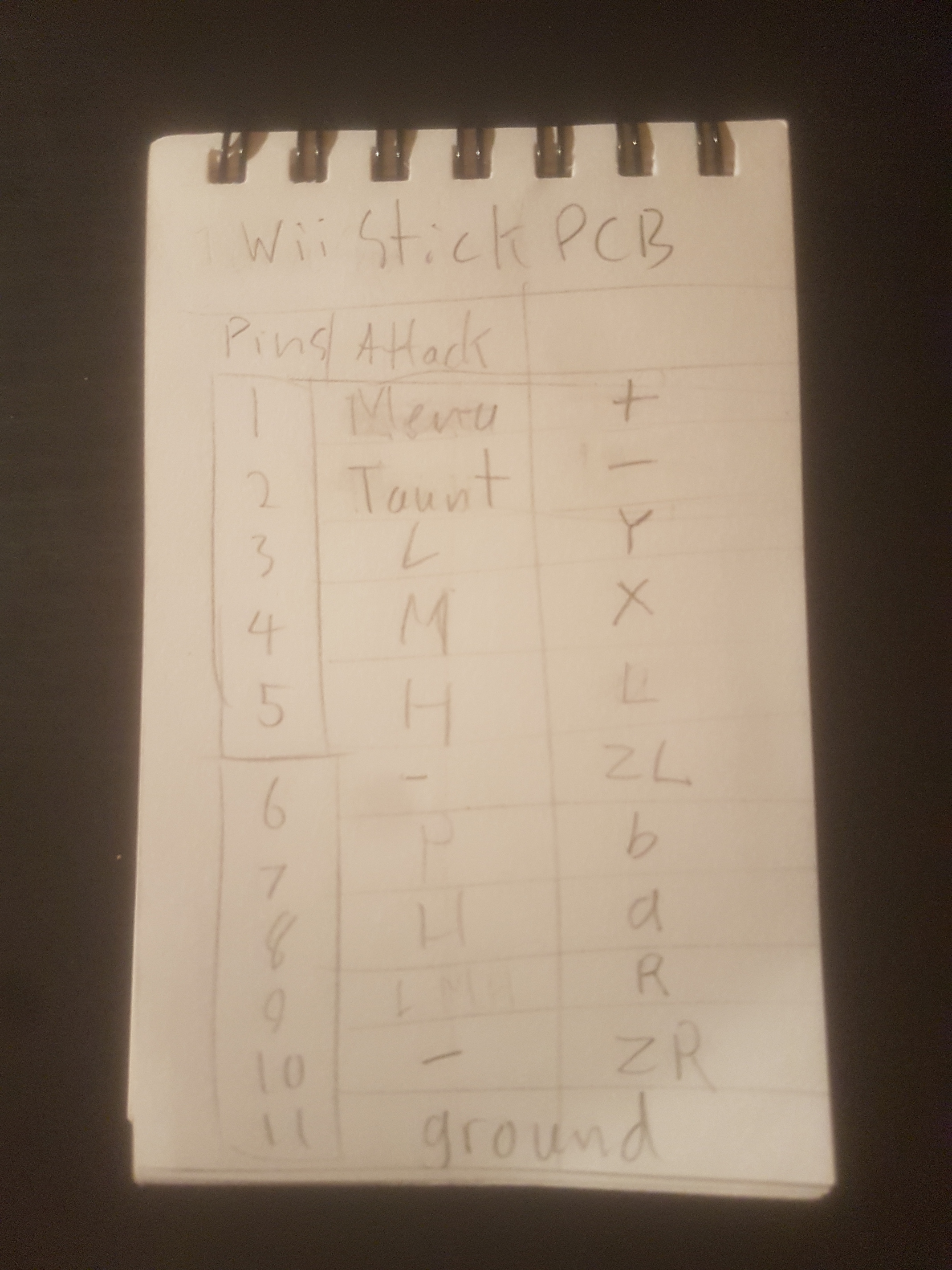
Edit: I got some of the connectors I need, and I think honestly I just have to connect the 10 buttons to the connector and daisy chain the ground, 11 in total and then just figure out which pins on the board are what. I tried using a multimeter to find the ground but I failed. Any tips on that?
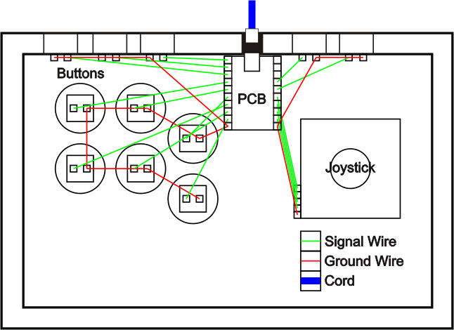
Just to update, I learned these are the basics of wiring based on diagrams like the one below, albeit this PCB is different, has a separate place for the joystick with another ground. The wiring before was just over-complicated so you couldn’t mod it easily without their own cables. I used a multi-meter to figure out what pins did what in a few games so I pretty much know where I’m gonna wires it up to a terminal block that will fit where it’s missing for the 10 buttons and just lead a ground into where it should go with a few 5 and 6 pin connectors. Got a few 2pin for the upper buttons, too.
I may ask for more help, but I’ll be surprised if something comes up at this point. Just gotta use a steady hand for a bit of crimping.
Yeah it sounds like you’re on the right track. If there are 10 switches and 11 wires, then it’s pretty likely that 10 of those wires each go to one side of a switch, and the 11th wire is common and goes to the other side of ALL the switches.
Often the common would be ground. The 10 signals would be normally “high” and pressing a switch would “pull them low”. It’s also possible that it’s the other way around: they’re normally low and that pressing the switch “pulls them high”. In any case this makes no difference to wiring.
You just need to figure out two things:
Which wire is common - You can probably probe around with a DC-mode multimeter by putting the black probe on a known ground, and touching the red probe to each wire. If you find 10 wires have voltage, and one does not, you know the latter is a common GND.
Which button goes with which other wire - this is just a matter of trying the controller out and mapping the function of each wire when it is touched to the common.
After that it’s just a matter of physical wiring. There are some terminal blocks at VHS on the shelves near the door to the woodshop. However I think you could just wire it like the diagram you posted, which the common wire snaking around to each button, and the rest of the wires just going directly to its button.
VHS has solder, irons, lots of scrap wire, heat shrink tube, heat guns, multimeters, etc. If you want to tackle this project on a Tuesday night you’d be most welcome.
Thanks! I’ll come on over if there’s an issue or to do most of the building, I have some of those supplies but that’s great to know there are extra tools and part there. I’m ordering wire from and arcade shop, color coded like the original was, and they have disconnect tabs that make modifying buttons easier, and a daisy changed wire that I’ll use for the ground.
I would wire it directly but I think I’ll use a terminal to try and keep it clean, separating the button wires from the wiring to the connectors. I found a 10 pin terminal that could mount where the old one used to be, so I may do the buttons there and route the ground directly to the connector. Luckily the stick itself has the buttons labled on the artwork, so I know which button will be which.
Thanks again for the help. I came into the open house last week and didn’t really talk to anyone but got a few wiring tips while tours were happening, I didn’t really have the right crimping tool for wires this thin on me or at the hackspace so I had to just brute force with pliers. I was missing a few pins so I had to finish some wiring at home but it was great to see the space. In conclusion, the basic wiring worked just fine for what I needed and I didn’t mod much else about the stick. The buttons I bought were a little tight and I didn’t feel like filing them down to fit just yet. Turbo works, I just didn’t know how to use it but looked up how and it works fine.
I’m definitely not afraid of modding sticks anymore! It was pretty simple wiring in retrospect.