Adapting toy wands for MMC

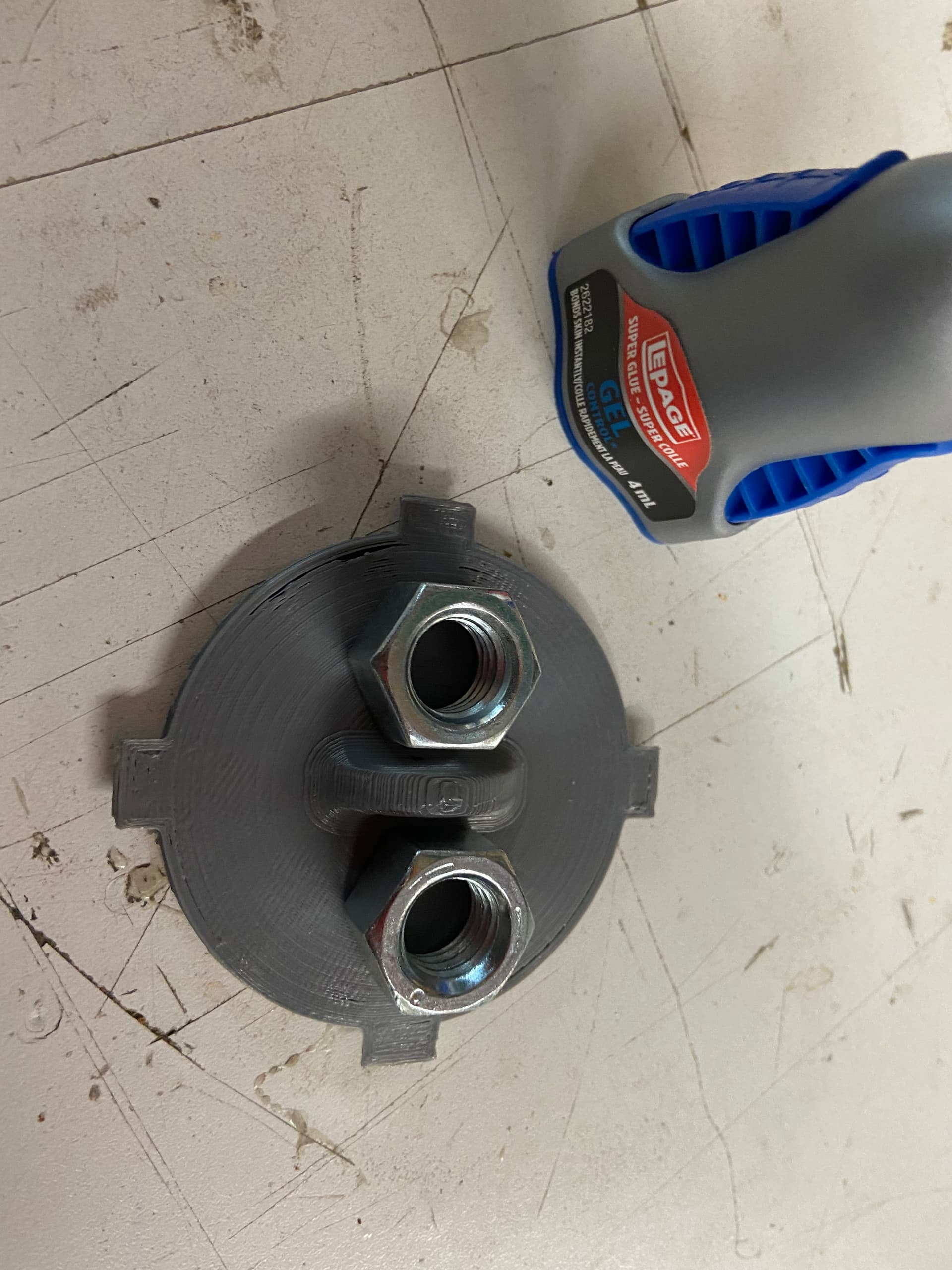
Here are the STLs for the stand.
bottomCover.stl (183.4 KB)
WandHolderBody3.stl (673.5 KB)
they are designed to be printed with 0.2mm layer height, but for the body, i recommend slicing using prusa adaptive layer height to shave some time off the print.

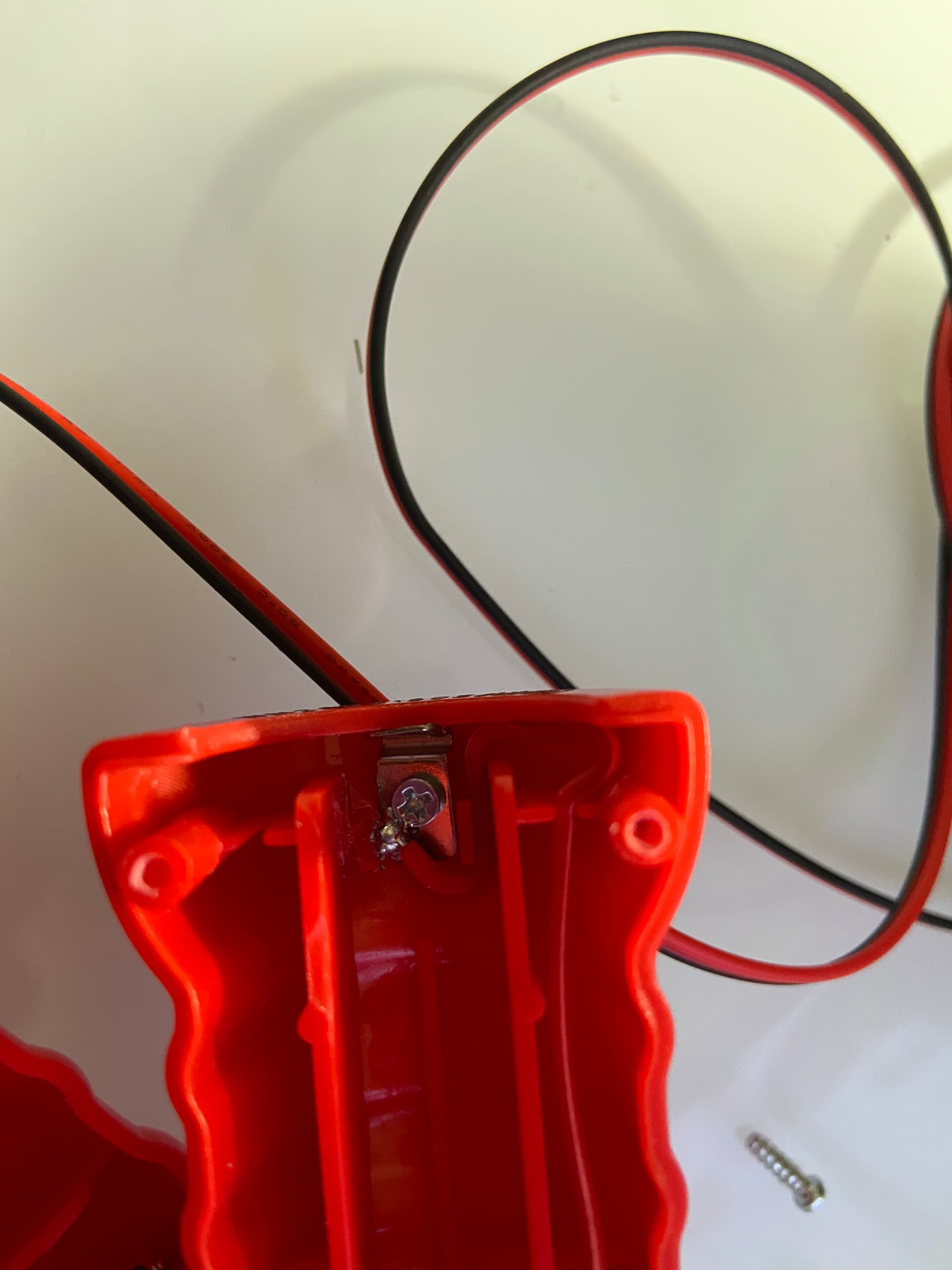
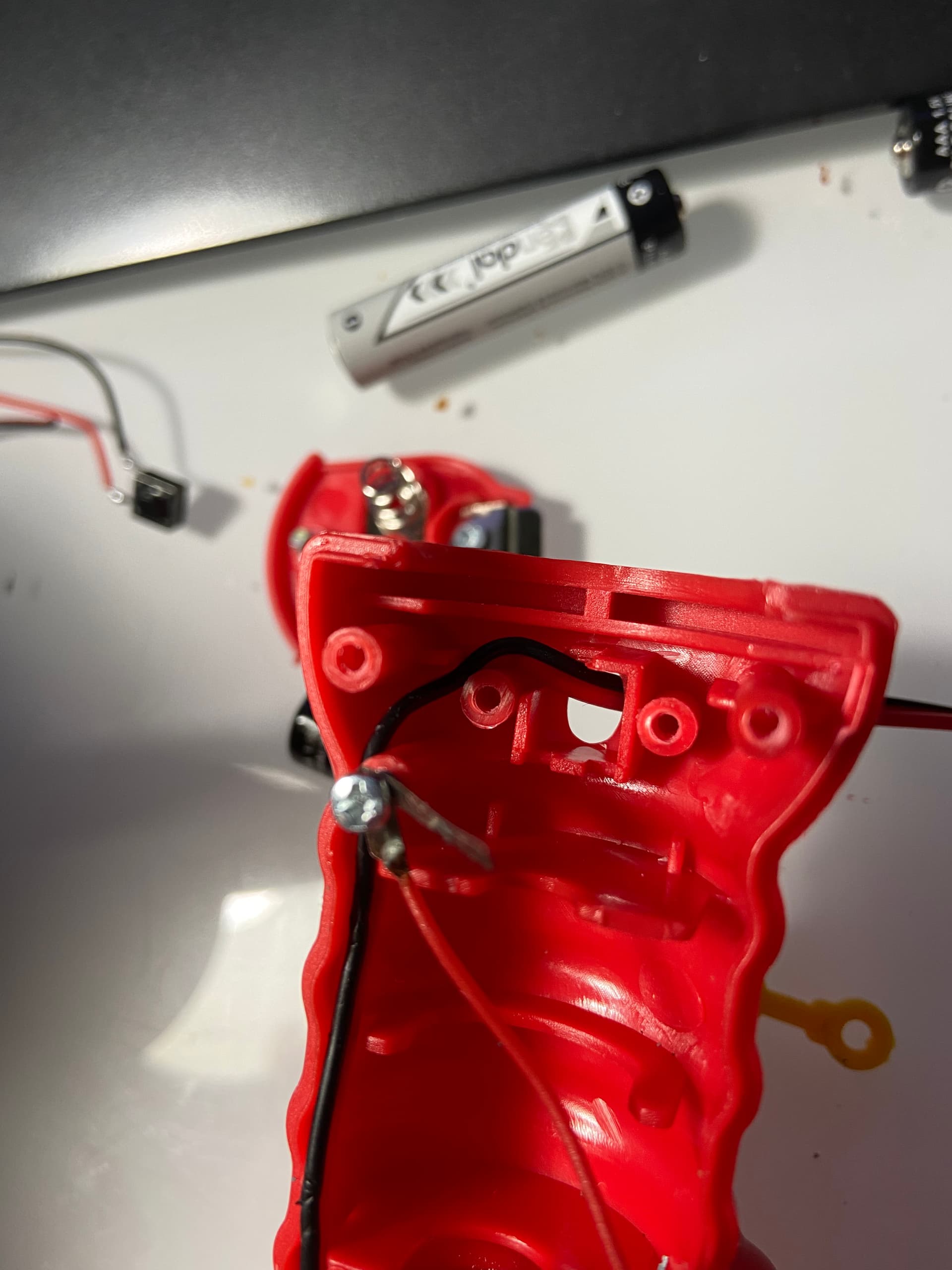
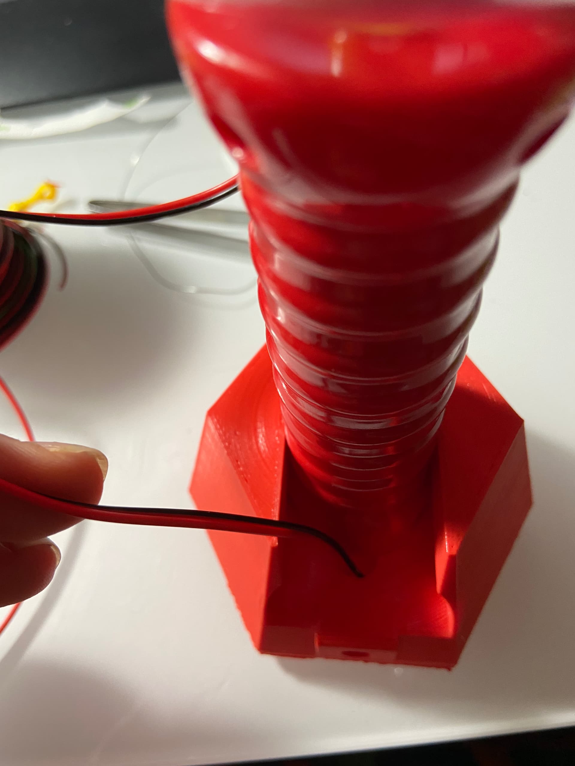
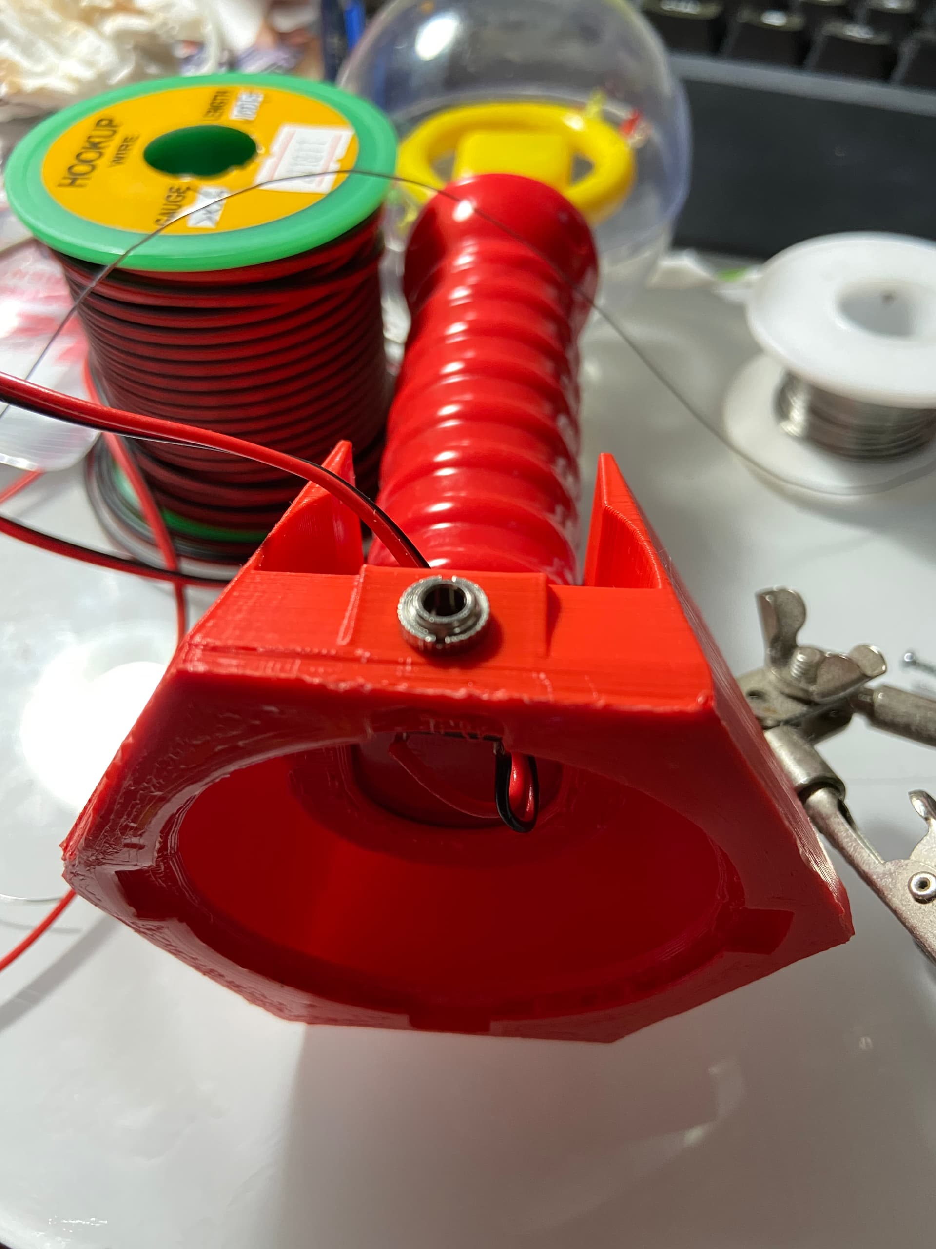
The idea with this hack is that we are removing the button, and replacing that with the mono jack to work with switches. Conveniently using the hole left by the button to allow for routing of wires, thus removing the need for drilling additional holes.

Instructions below :point_down:

3 Likes

supply / cosumable

  • 1x Wand Toy [@chadleaman please add identifying detail for this particular brand]
  • 1x bottomCover.stl (183.4 KB) [printing instruction above :point_up:]
  • 1x WandHolderBody3.stl (673.5 KB)
  • 1x mono jack [@chadleaman please fill in the part detail]
  • ~20 cm of 2x26AWG multi-core wire, or 2 pieces 20cm regular stranded wire (24~26AWG)
  • hot glue
  • solder

tools needed:

  • #0 phillip screwdriver
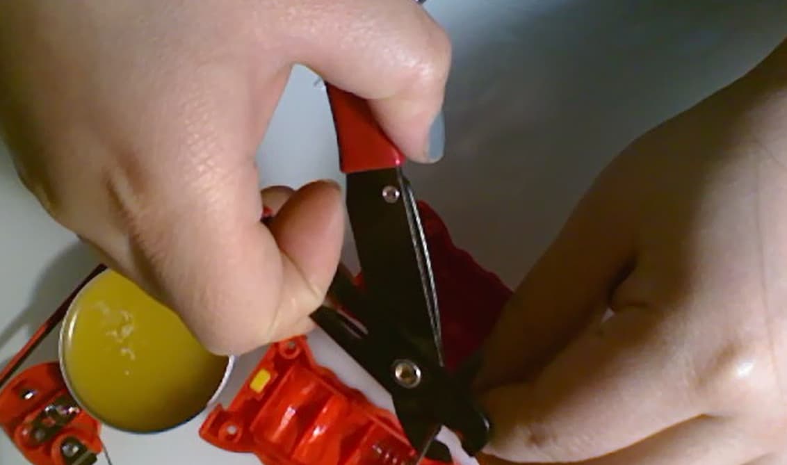
  • flat head screwdriver for prying
  • soldering iron
  • hot glue gun

how-to

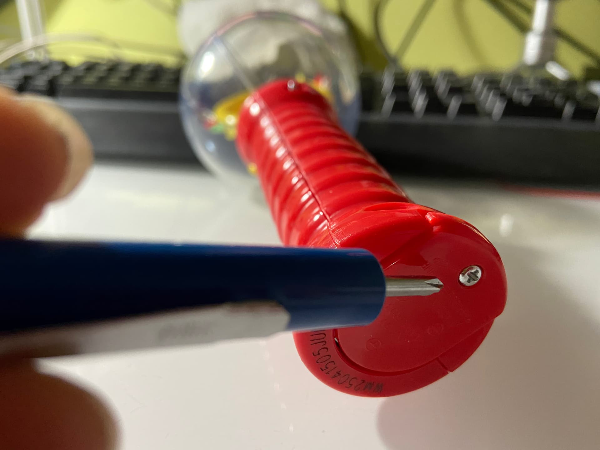
  1. Loosen the screw and remove the battery cover.
    Caution: the springs on these battery contacts are pretty loaded, the batteries may temporarily become projectiles.
    Remove any battery that did not eject itself.

  2. Unscrew the four screws marked in image below

  3. Gently pry apart the two half of the handle along the seam using a flat head


  4. Once the handle has come apart, unscrew the screw marked in photo and remove the piece of metal contact. Keep screw for later reassembly.

  5. Gently pry the clear globe free from the button half of the handle.


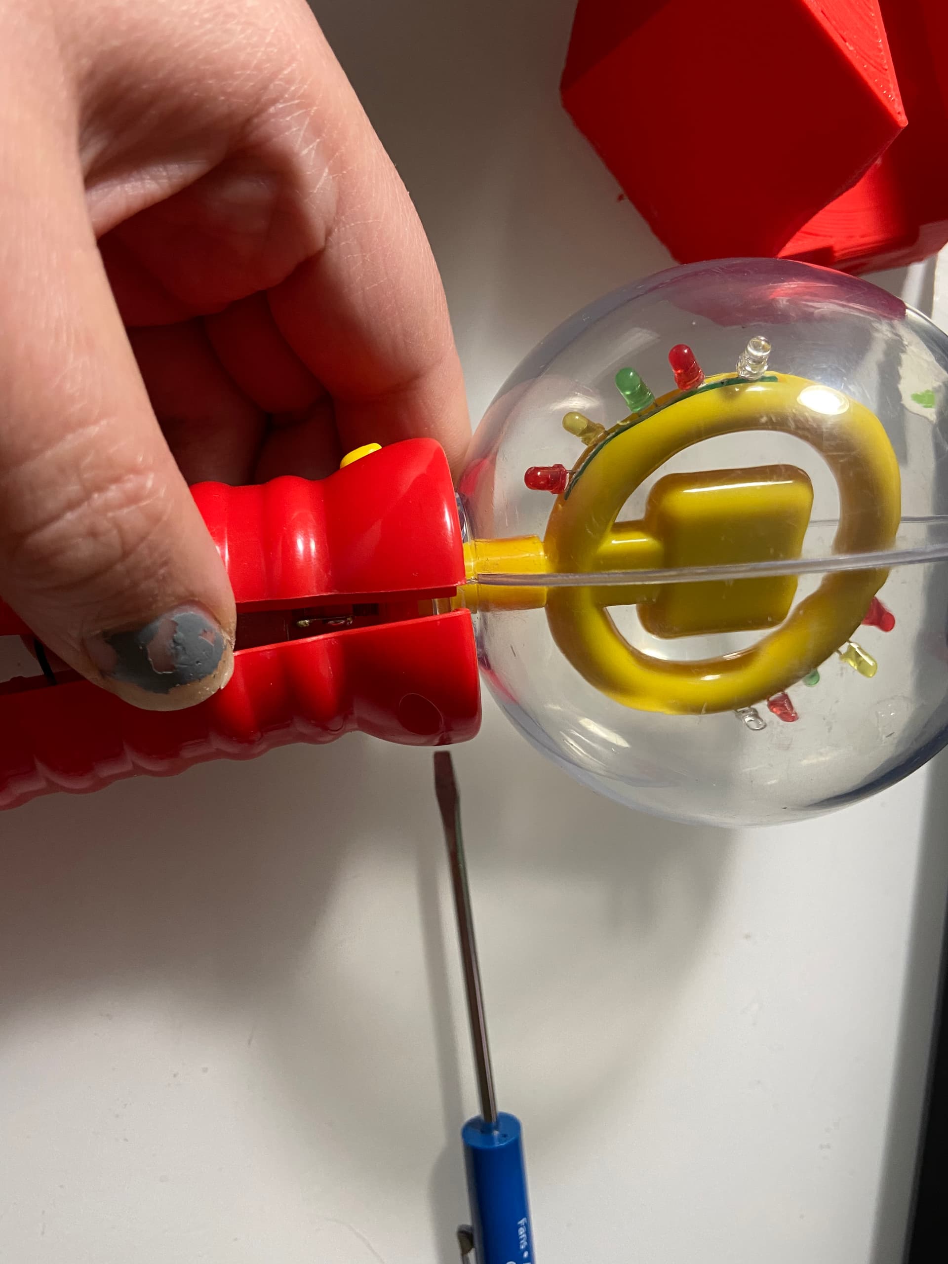
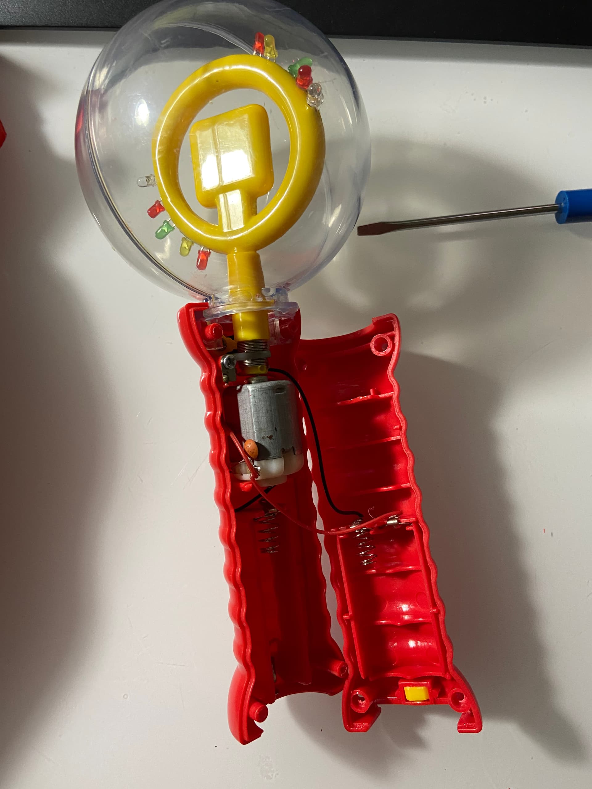
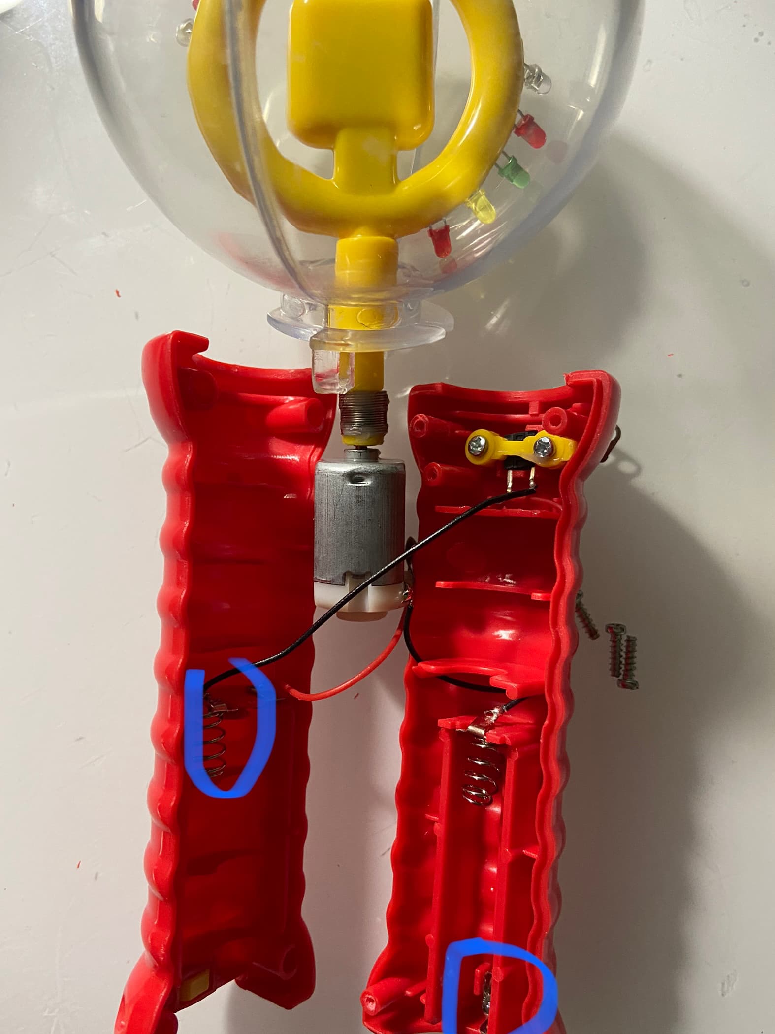
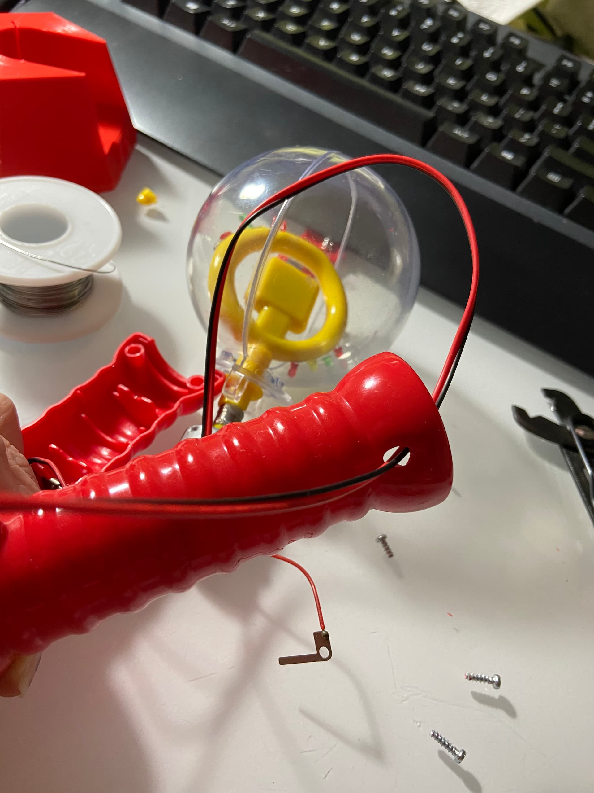
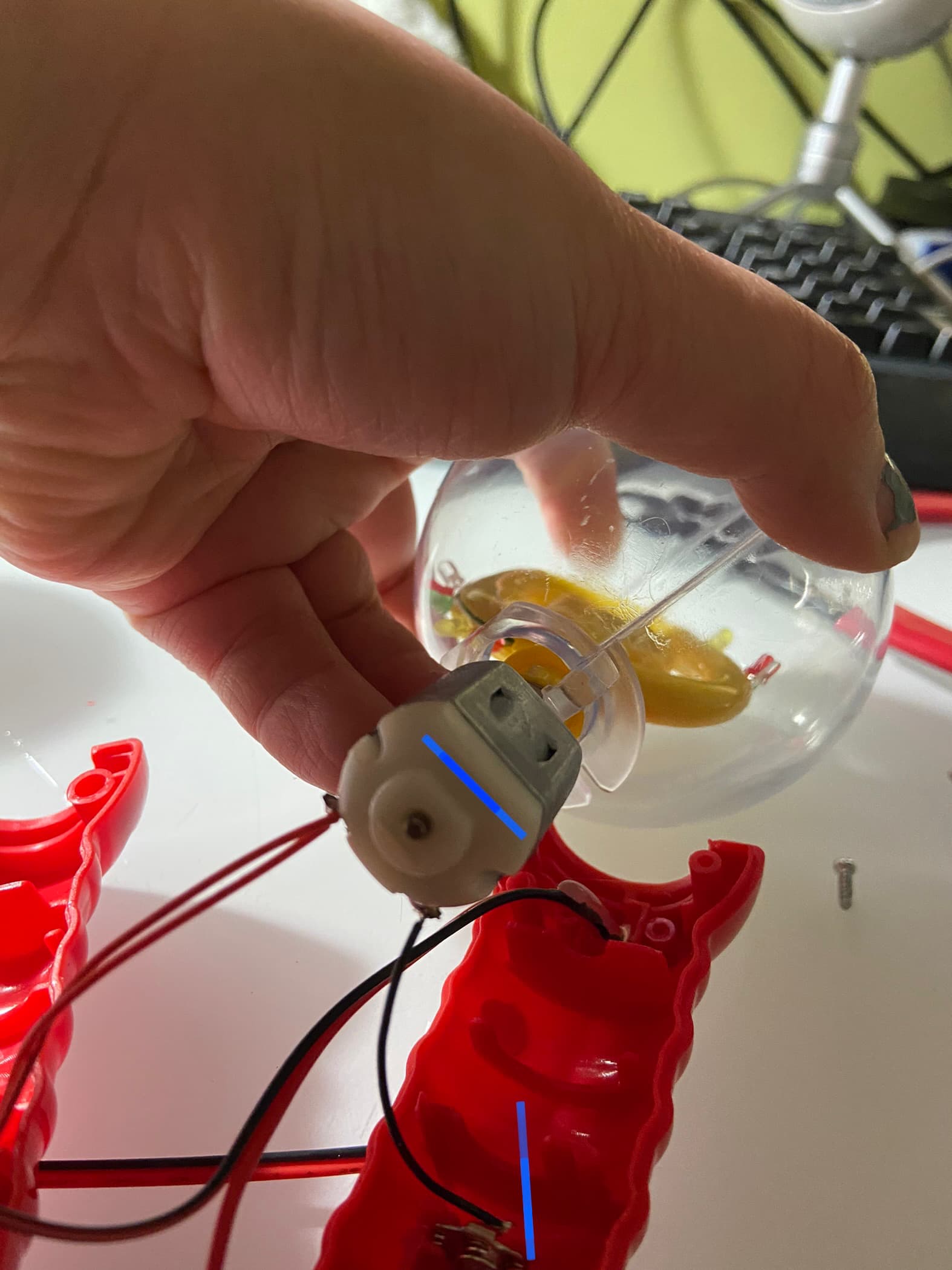
    The motor and the clear globe is part of the same assembly, carefully lay all the part out, and try and avoid putting strain on any of the solder joints

  1. De-solder the wires at points marked on the photo below

    For the bottom red wire, it may be easier to you unscrew and remove the metal clip from the plastic shell first
  2. Unscrew the screws attached to the yellow piece shown below. Remove the entire button assembly. They are no longer needed.
  3. Split !5cm of the wires if you are using multi-conductor wire, strip the red wire
  4. Solder the red wire to the bottom metal clip and route the wire as shown below
  5. Trim back the black wire, the length of black wire should reach the battery clips in the middle of the handle. Strip the black wire.
  6. Solder the black wire to the battery clip.

    12.Thread the wires through the button hole. avoid too much slack wire inside, it might interfere with the moving bits.

    Route the wires through the inside of the handle as shown,
  7. Apply hot glue to fill up space between the wire and the hole, to add strain relief to the wire
1 Like
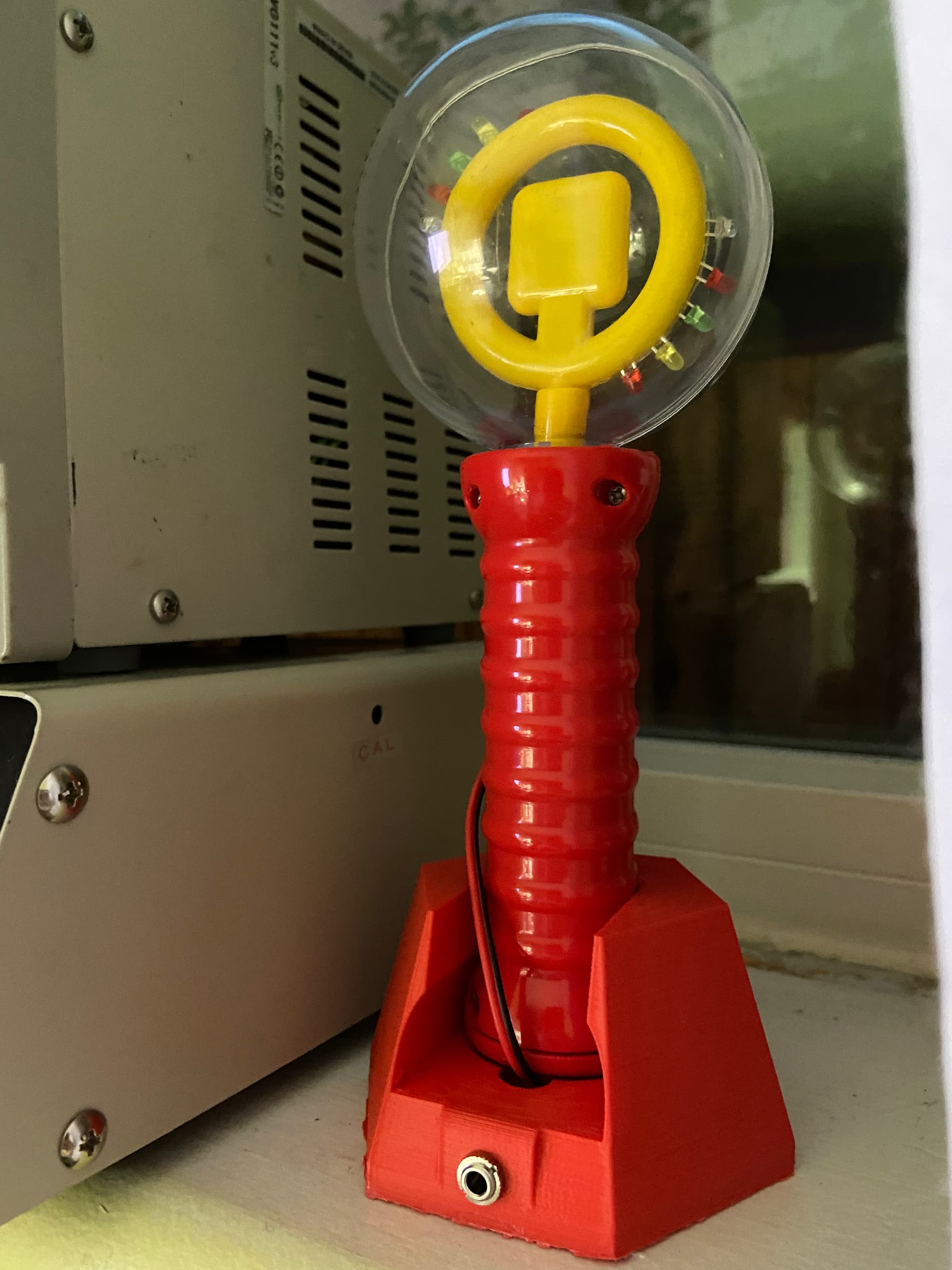
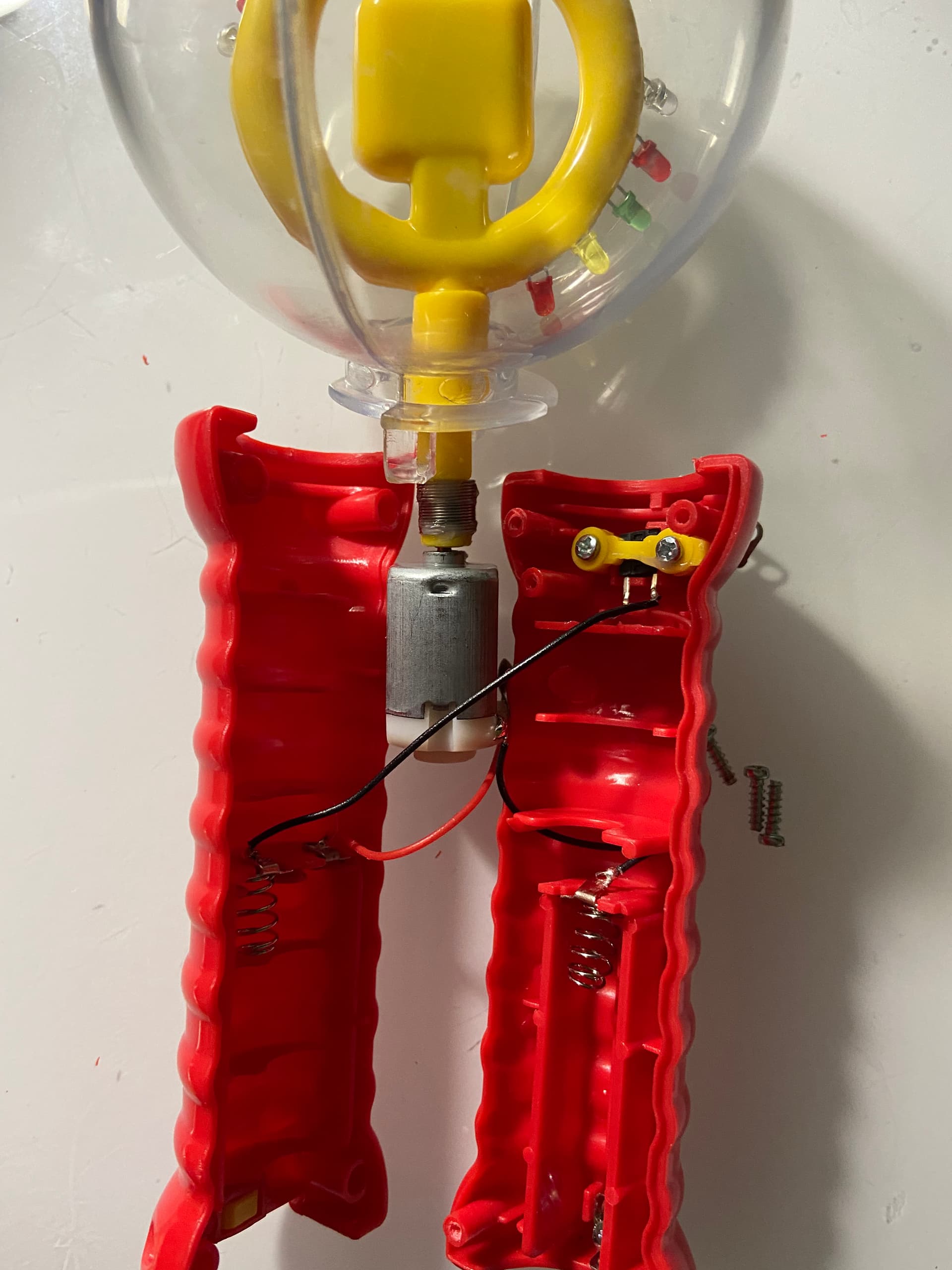
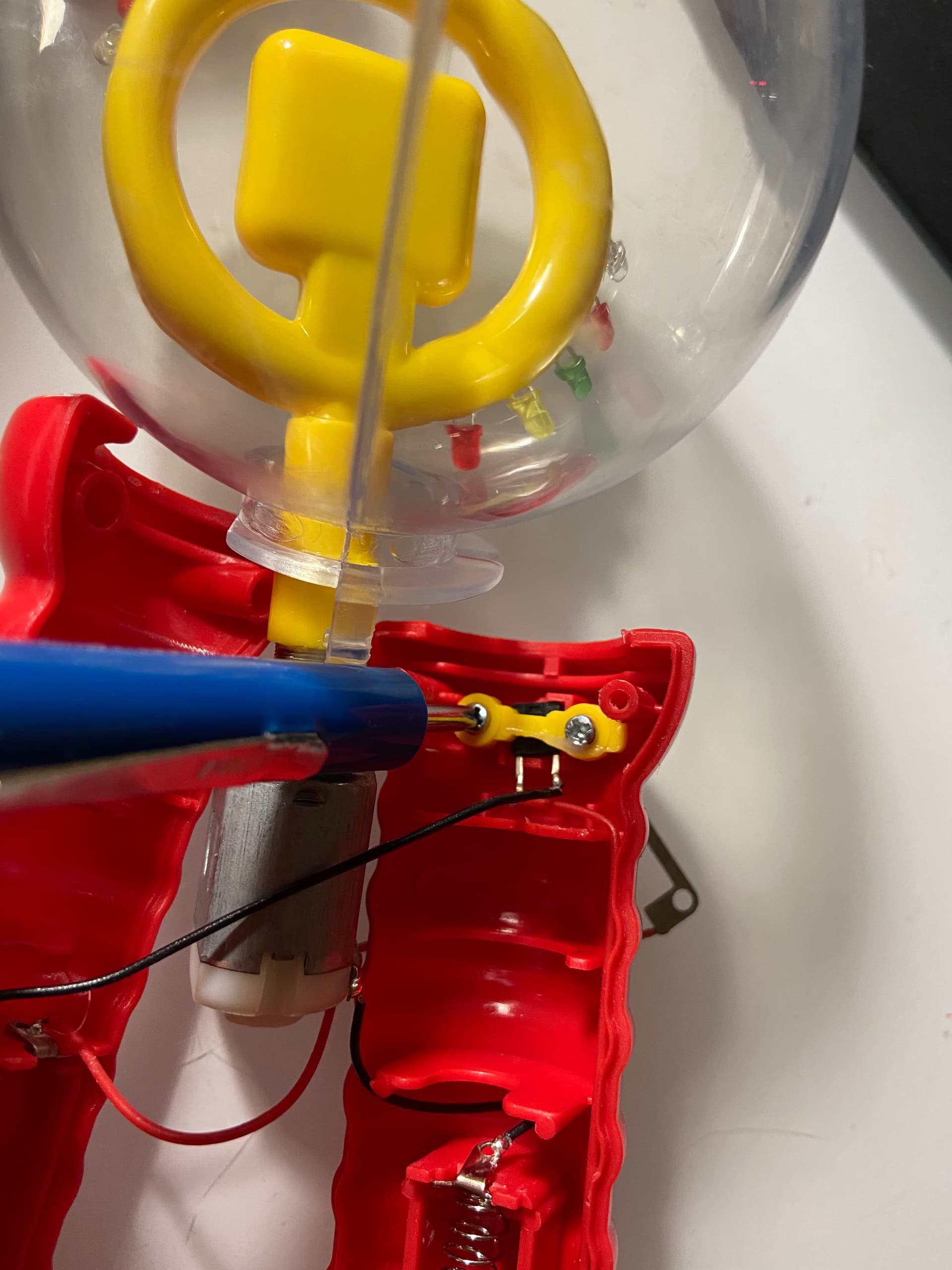
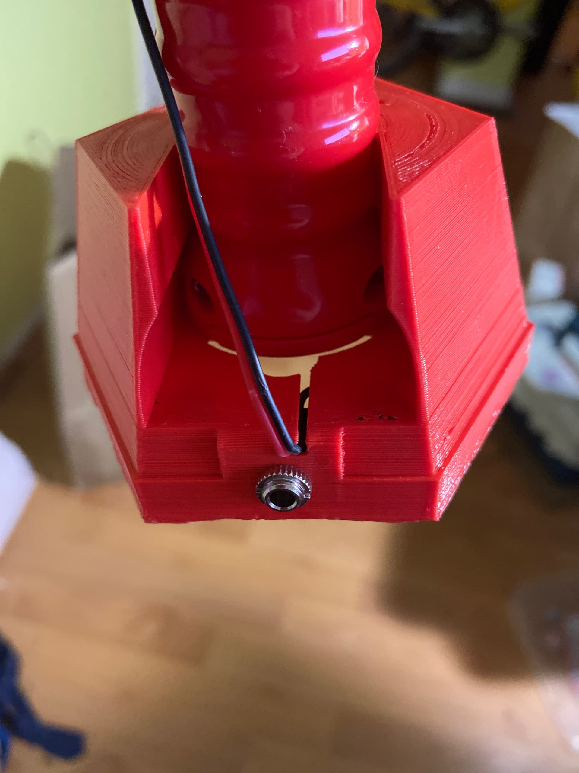
  1. Start reassembling the wand by putting the globe and motor assembly back into the half of the handle with the button hole
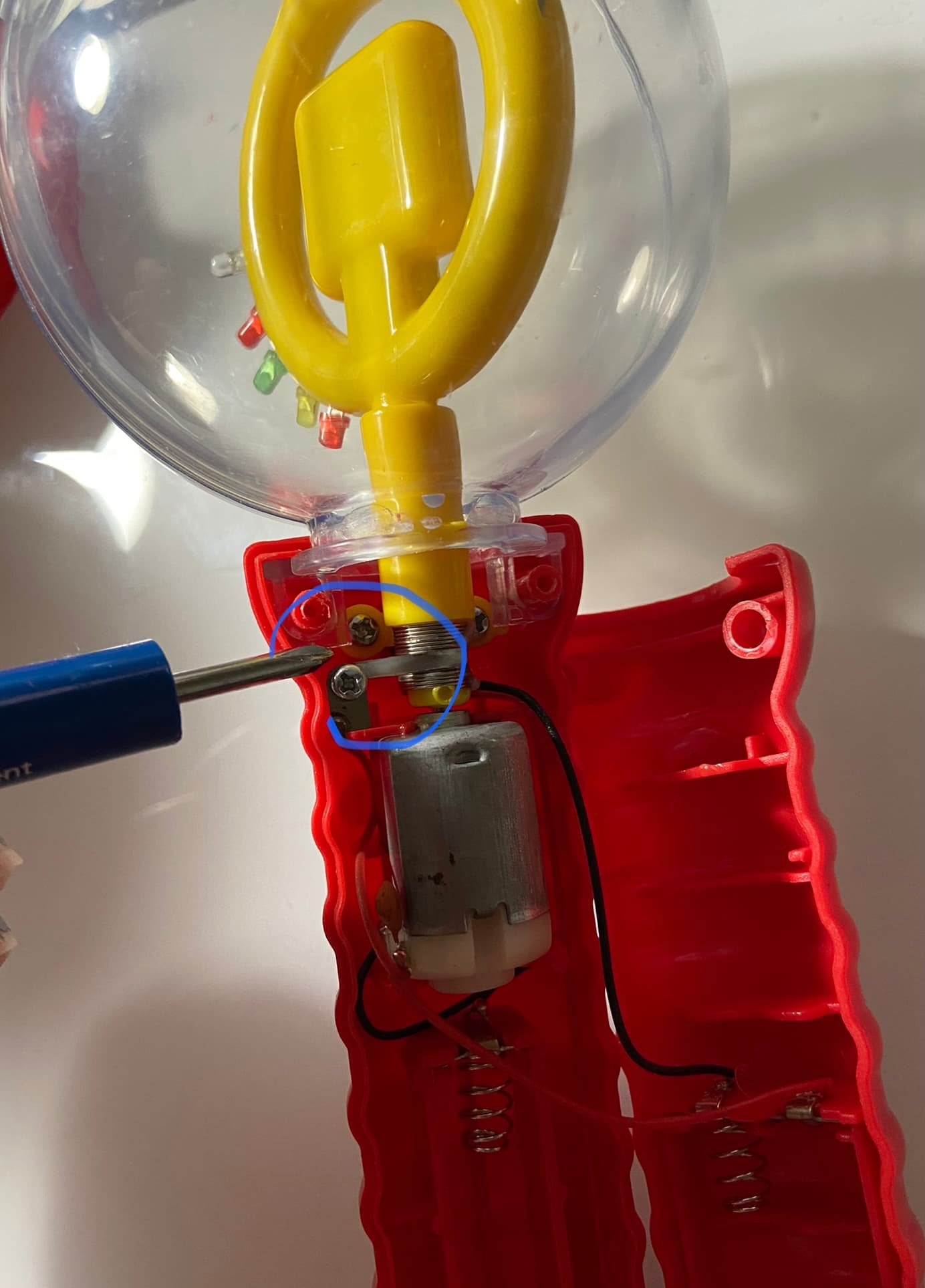
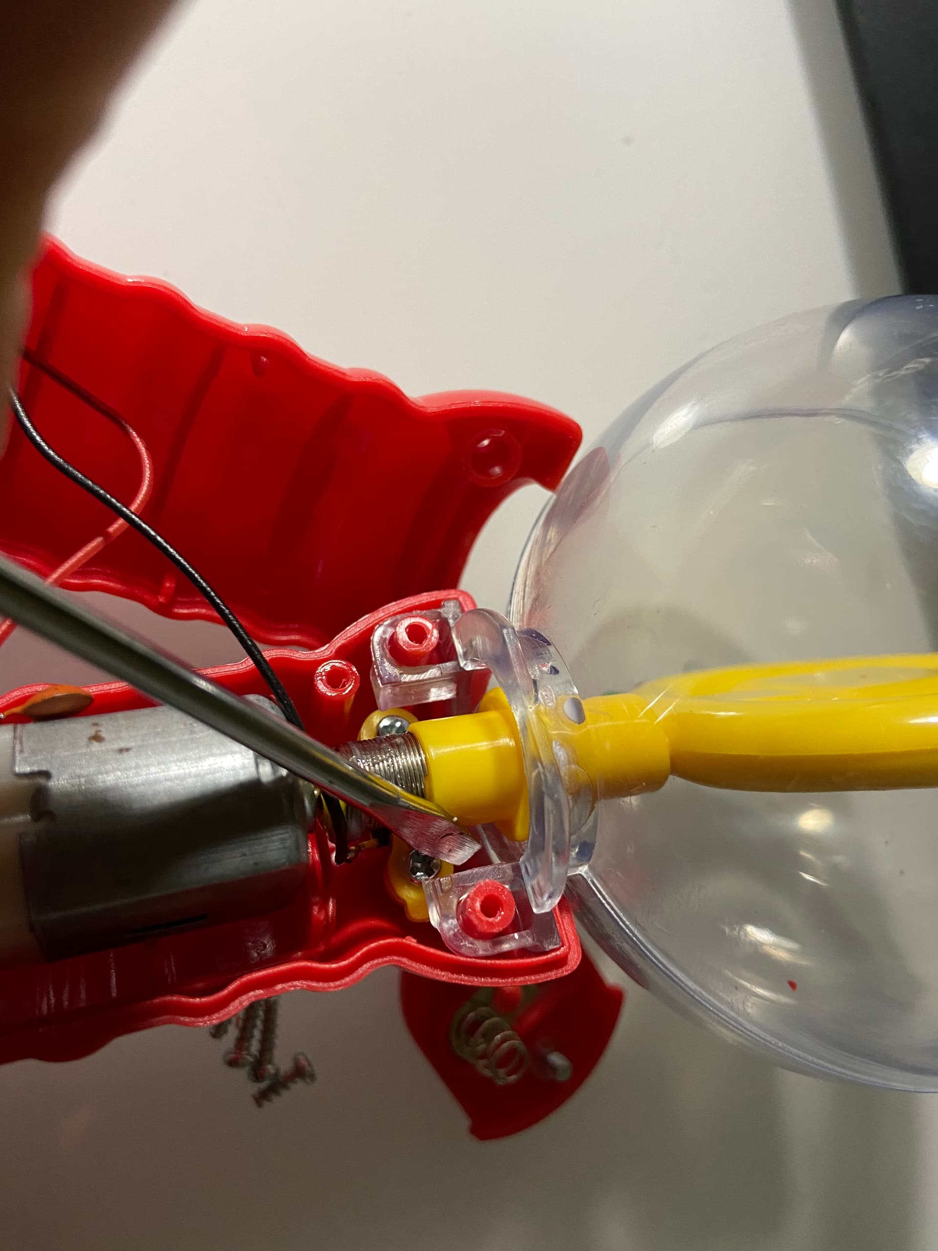
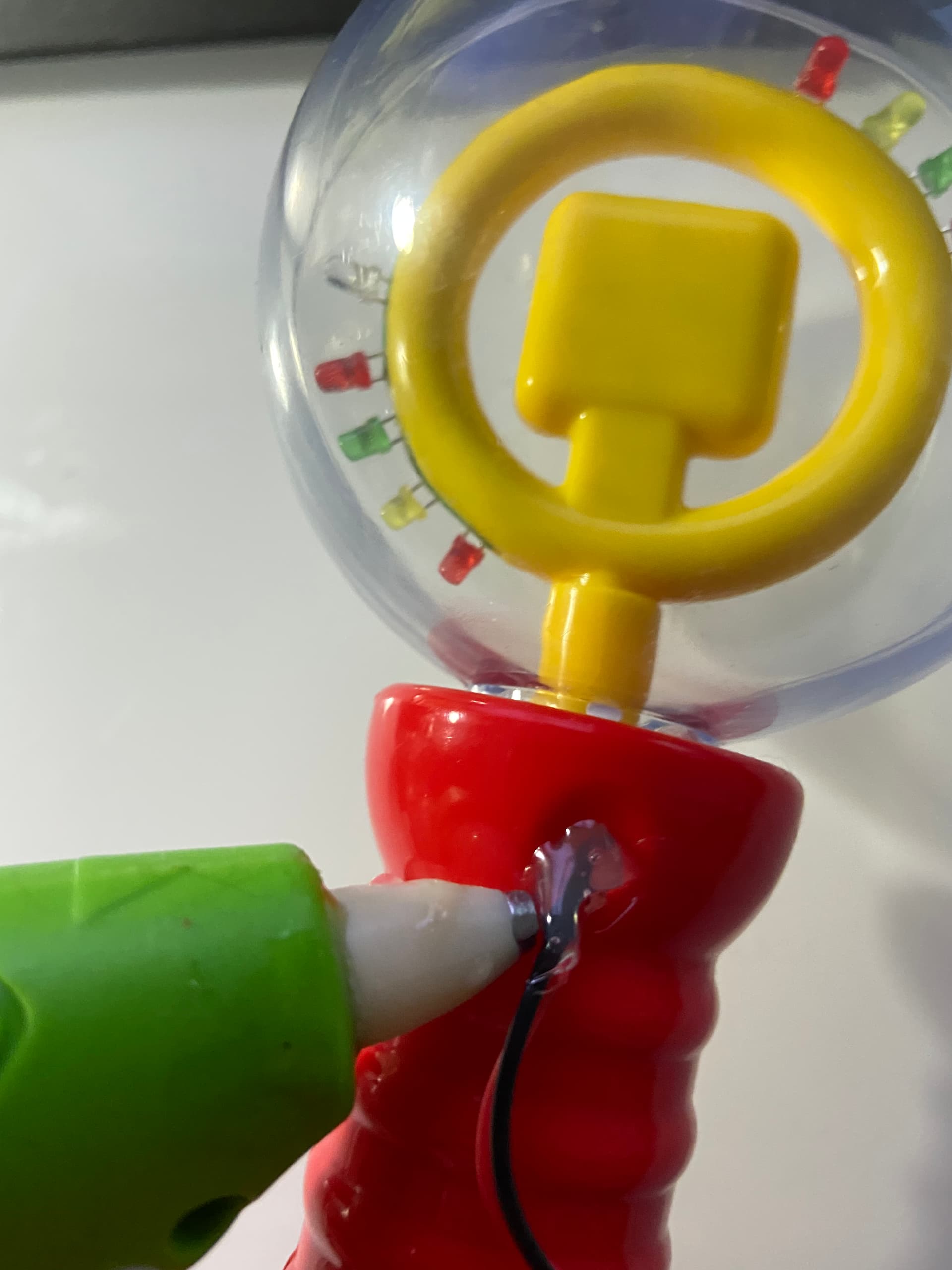
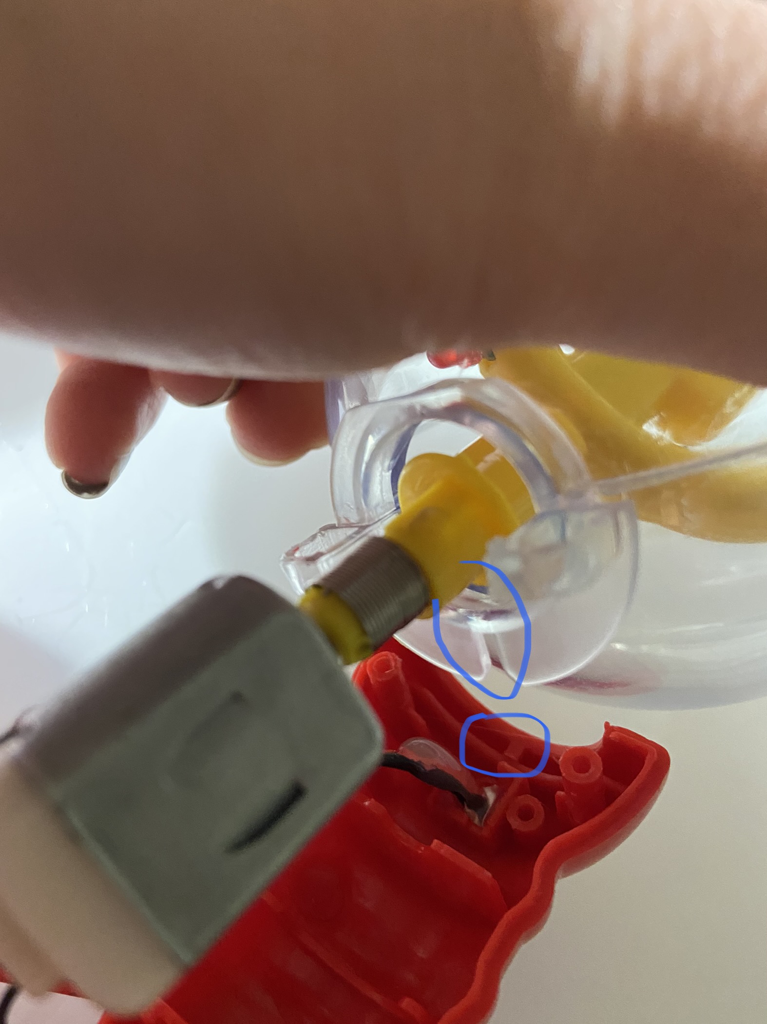
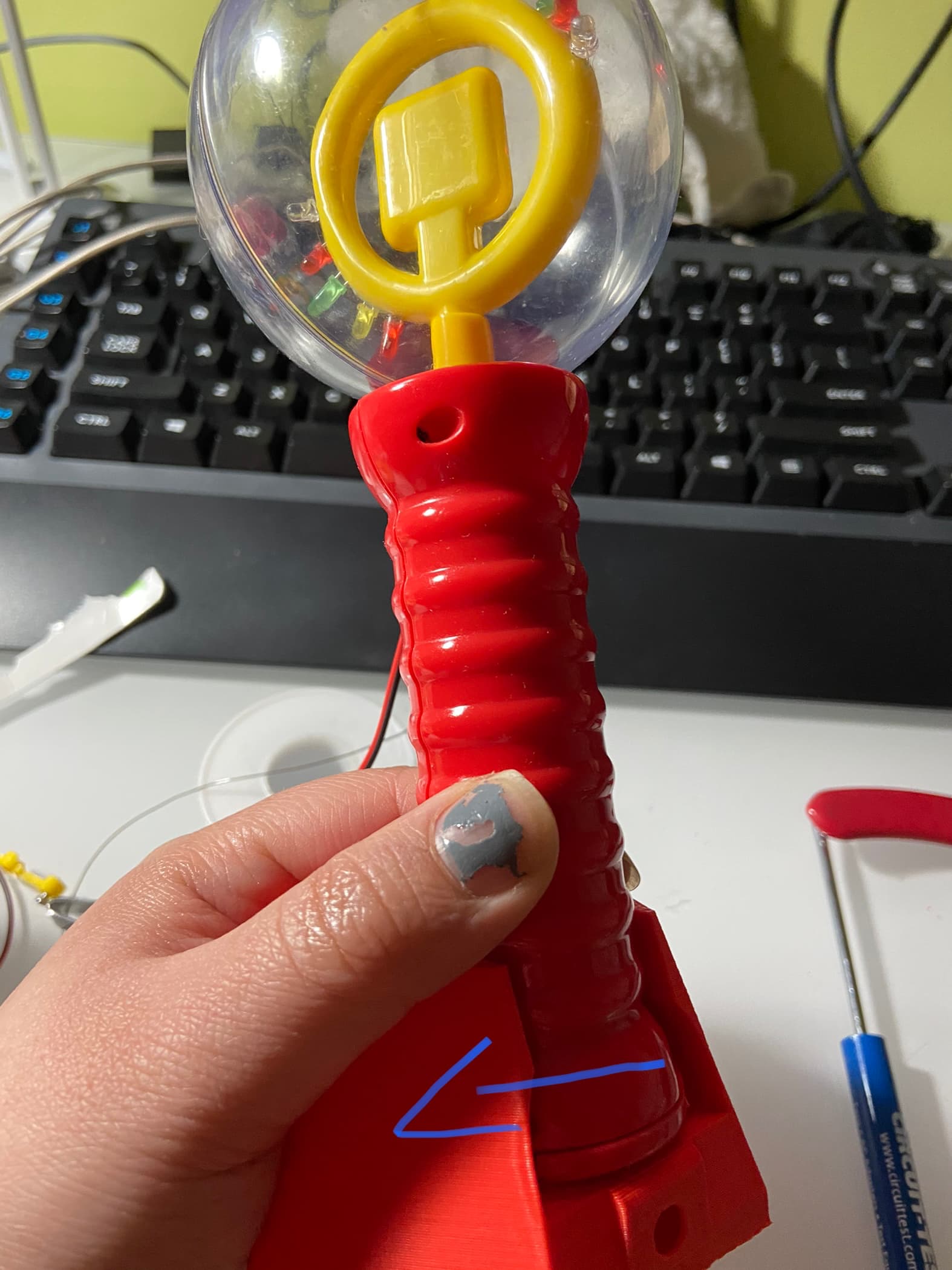
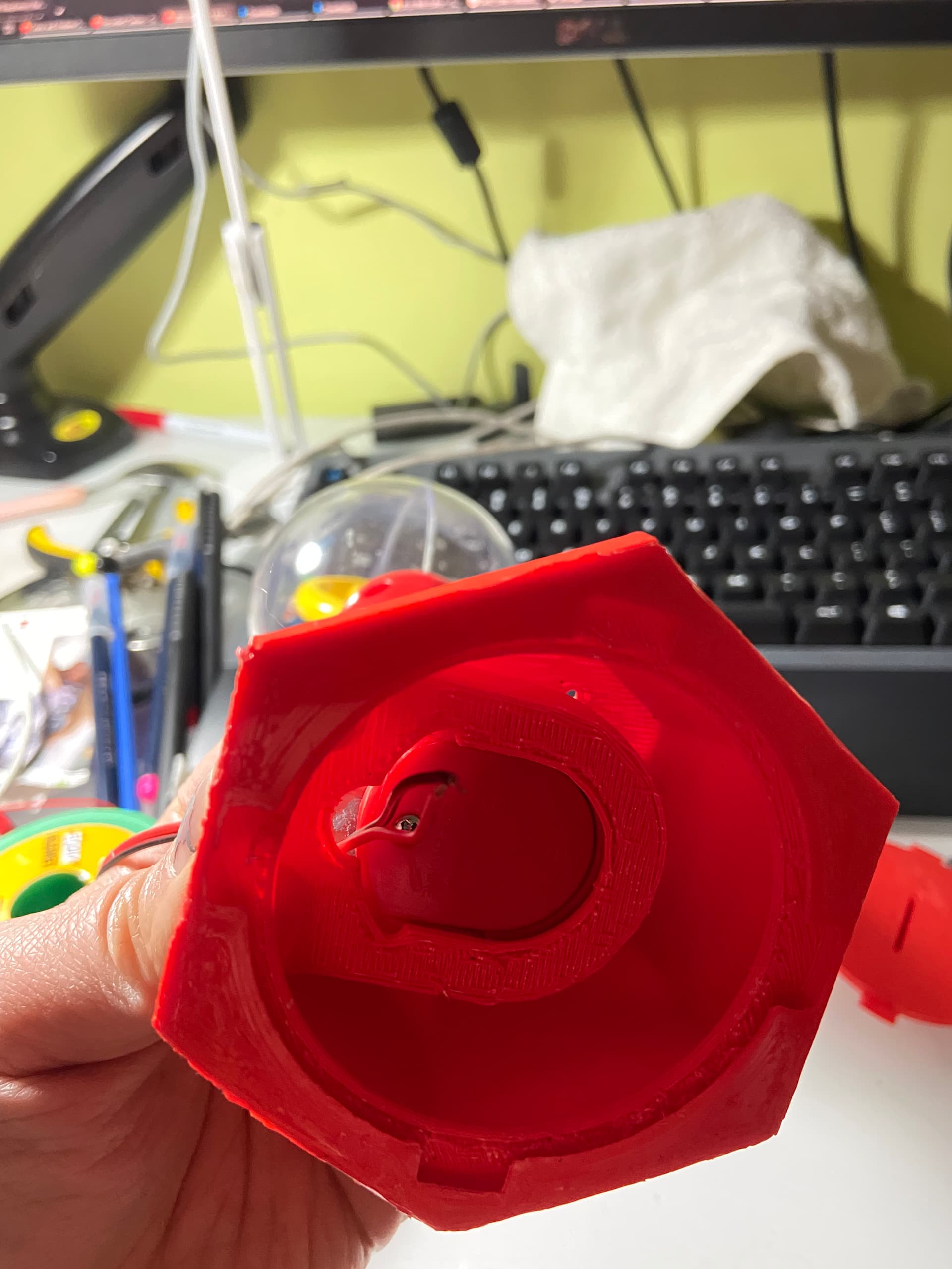
    Note the alignment of the motor and the clear globe. See photos below


  2. Reattach the L-shaped metal contact

  3. Snap close the handle, being careful to not pinch any wire inside.
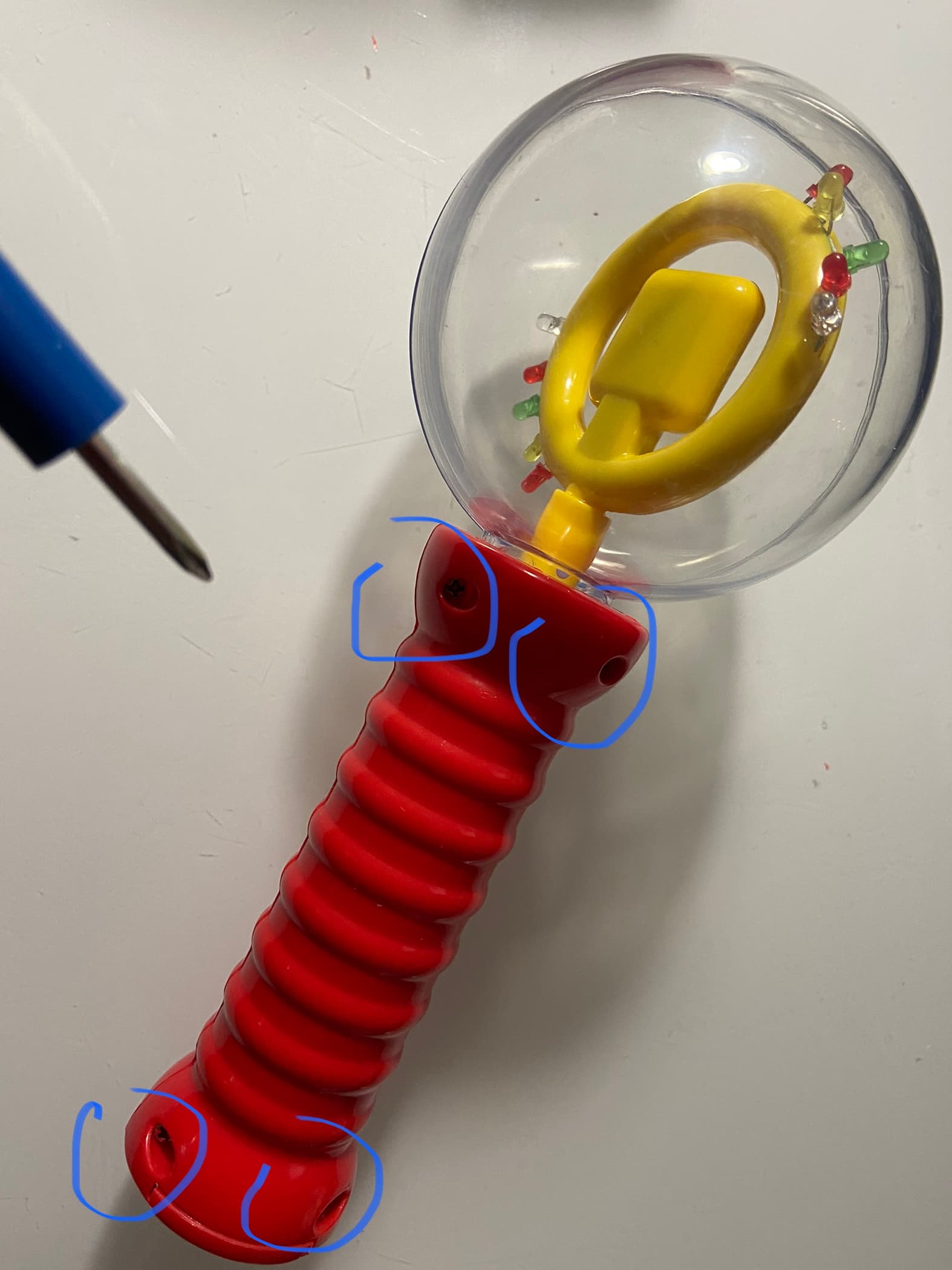
    Replace all four screws.
    Re-insert battery and tighten the battery cover screw

  4. Now is a good time to test the result of the hack.
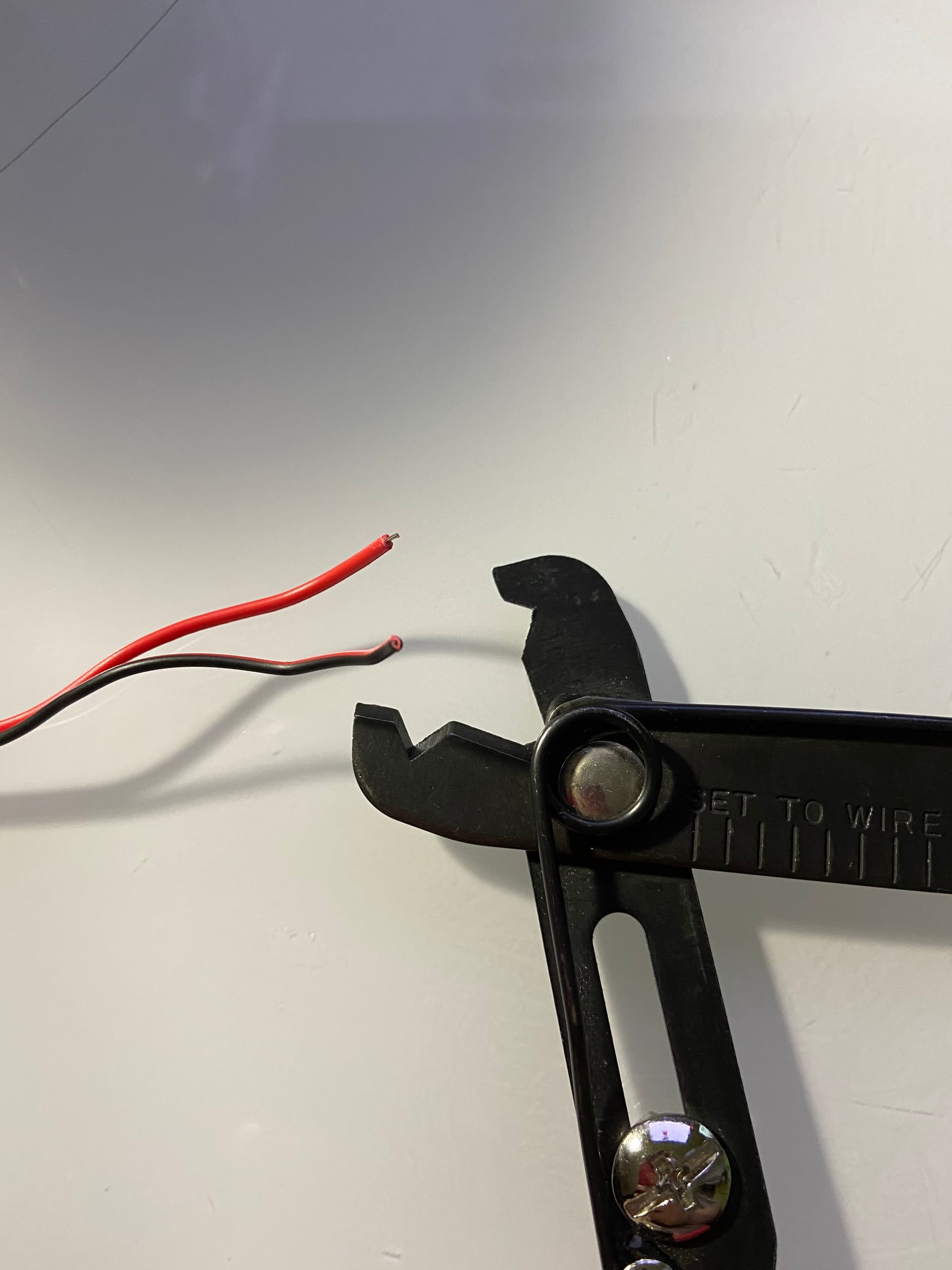
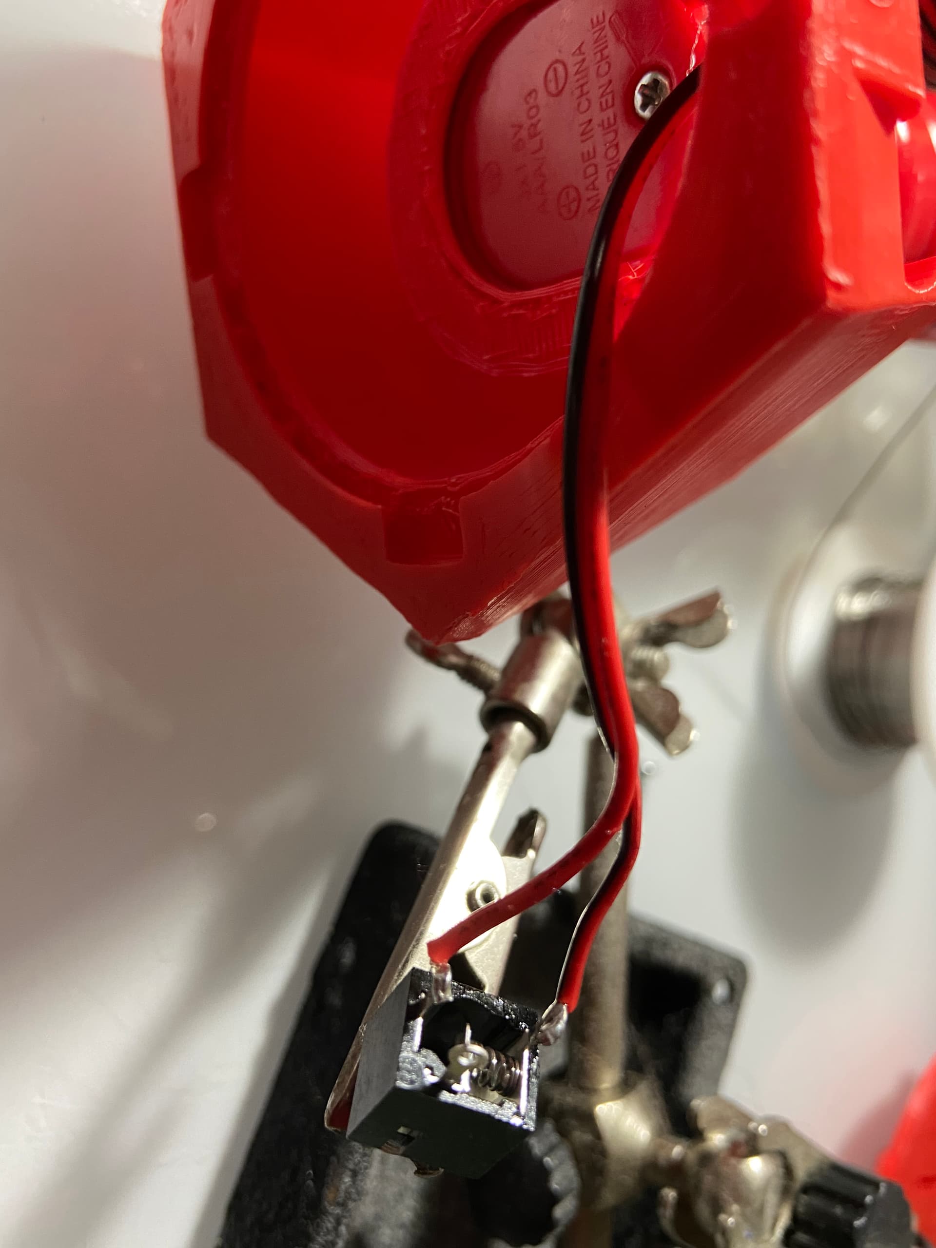
    Strip the other end of the wire and touch them together. If all goes well, the motor should spin and the light would come on. If not, open up the handle and check:
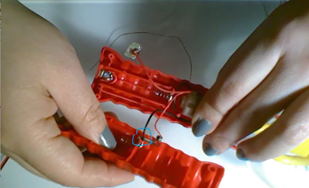
    – wiring, no cold solder joint or frayed/pinched wire
    – mechanical interference, the axle may be rubbing up at the some wires
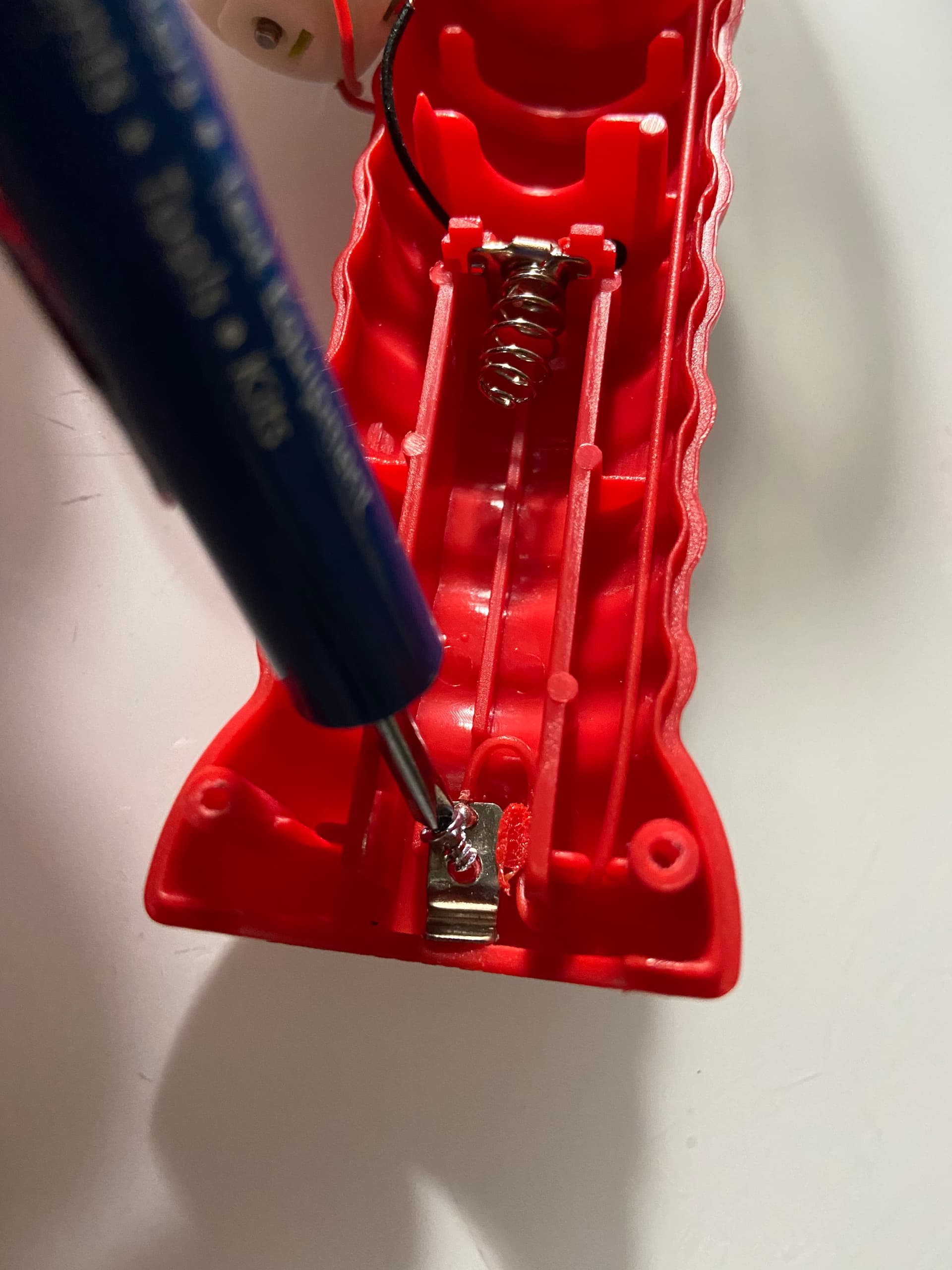
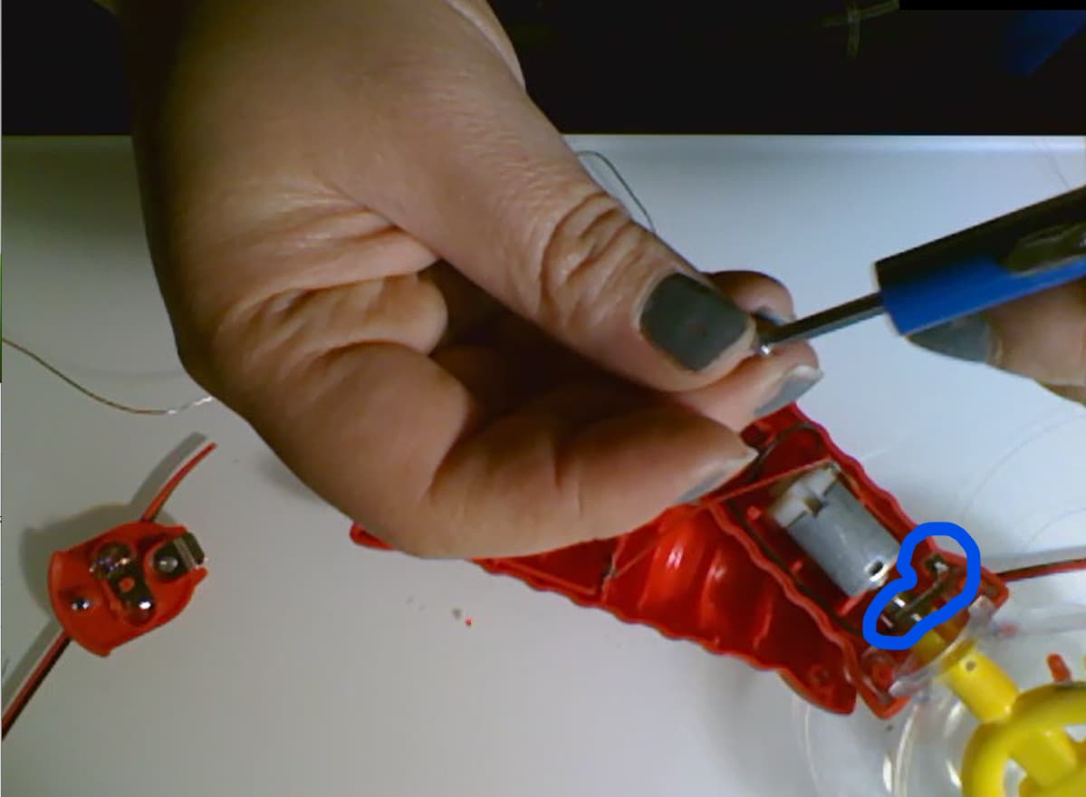
    – The L-shaped metal piece isn’t making good contact against the spring around the motor axle.

  5. slide the wand into the stand.


    make sure the battery cover is lined up with the opening in the stand.

  6. Thread the wire through the opening of the stand.


    Solder the wires to a mono jack as shown in photo.

  7. Attach jack the the stand.

  8. Super glue something heavy to the bottom cover to weigh the stand down

  9. Close up the bottom with bottomCover.stl

4 Likes

MIMI! I can’t believe the TLC you put into this and documenting this. I’m going to pick up another one of these wand tonight and give it a go to see if it passes the “Chad test” (if Chad could build it, any idiot could build it lol).

Thank you for all the energy and time put into this one, you’re awesome!

2 Likes

I was doing that while bored sitting in a zoom class :shushing_face:

2 Likes

This looks like a fun hack! I love the base you designed also. Very cool.

I made another iteration of the base, added some better wire management:

2 Likes

This looks great @xquared, and would be a great addition to the library.

  1. Can you share original CAD files as well (e.g., Fusion .f3d - makes it easier for others to customize / improve)
  2. What sort of license would you like to use? We typically use a combination of CERN-OHL-P for the design and CC BY-SA 4.0 for supporting materials.
  3. Do you want to submit it directly, or do you want us to do it?
3 Likes

Put together basic documentation here in preparation for adding to the MMC Site: GitHub - makersmakingchange/Spinning-Light-Wand-Adaptation: Instructions and parts for how to make a commercially available Spinning Light Wand toy adapted for use with assistive switch.

I believe the Switch model is a CUI SJ1-3513 (https://www.digikey.ca/en/products/detail/cui-devices/SJ1-3513/738683). The toy itself is available in-store at Walmart: https://www.walmart.ca/en/ip/spinning-light-wand-yellowblue/6000201173987

3 Likes

Thanks Jake - good to know what switch model that is. Am I reading that right that it’s $2.40 per jack. I’m sure the digikey quality is good. Is that something you think would be on aliexpress for less, or would you advise to stick with digikey components?

This the jack used was this fella, have 100s at office of these. Slightly cheaper.

https://www.digikey.ca/en/products/detail/schurter-inc/4832-2211/2646631

1 Like

Good to know - thanks!

I based the jack model off what I saw in the 3D model, but now I see that doesn’t match the picture in Step 19. Maybe @Mimi can confirm the design intention there. (Should be enough space for either, or ideally add the necessary space to work with a variety of panel-mount jacks)

As for sourcing, the ideal case is a balance between ordering time and the cost of a single unit / single build. (There is nothing special about Digi-Key, we often use them internally for speed / selection / and since we often hit minimum order to qualify for free shipping). There is space in the BOM to add alternatives and that’s a good option if a maker can wait, or is making enough to justify buying in bulk.

Another option which can often be cheaper is to use the end of a cable with a female jack. Can often find these extension cable at local Dollar Stores. (Usually Stereo rather than Mono, but that can work)

Edit: (May also want to consider available quantity - the one I originally linked has ~70K, whereas that one has ~1.5K)

1 Like

Sorry i forgot to reply earlier. I think either is fine. I modeled up the old jack, but the cheaper one also fits.

1 Like