3d printed Gimbal

Thursday @JayTheDude approached me to ask me how to do a few things in Fusion360. I showed off a few tricks, but I wanted to remake the model as a completely procedural model and make my own bearings.

Thursday night I went home and modeled it up quite procedurally. You can change various thicknesses and angles all by variables, and everything adapts.

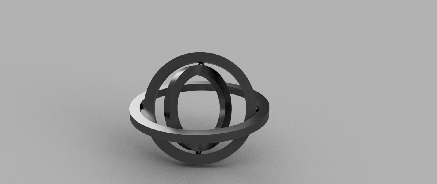
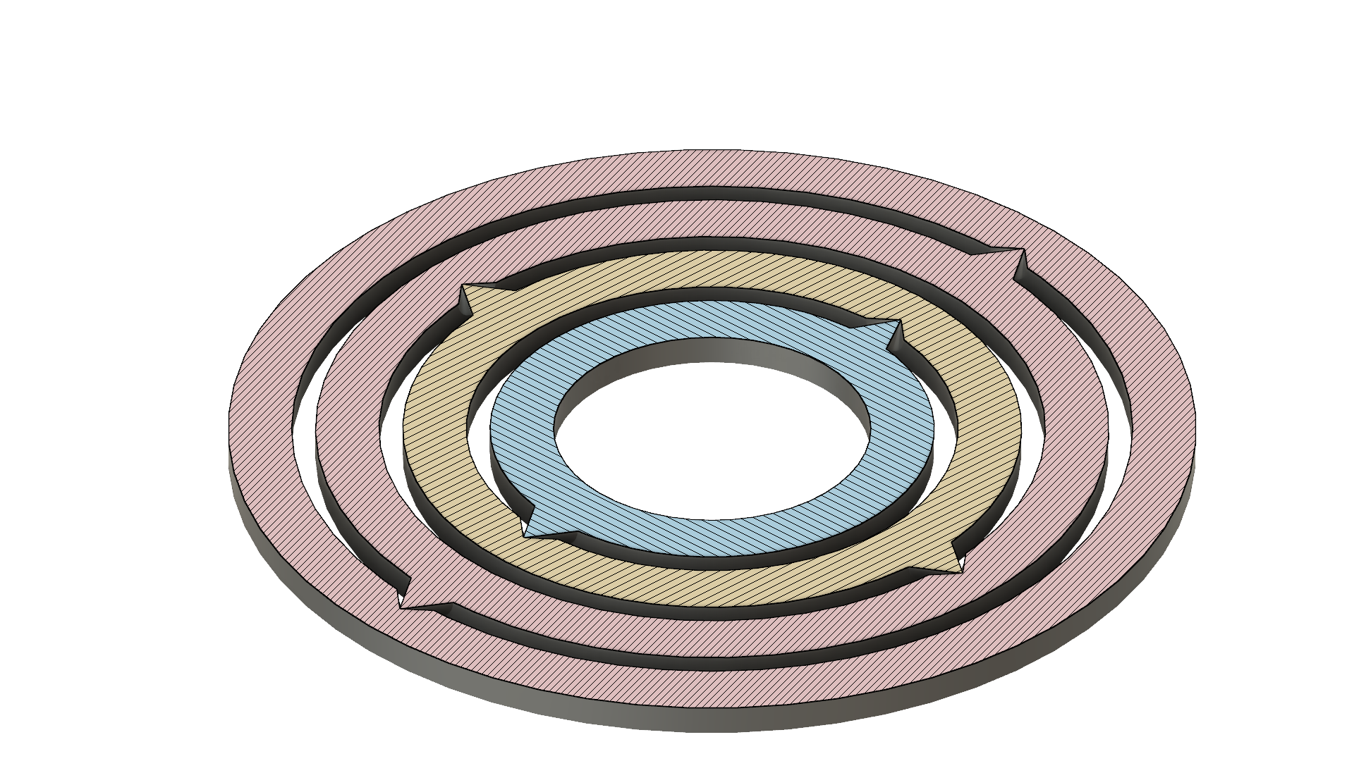
Here’s the CAD model rendering from Fusion360:

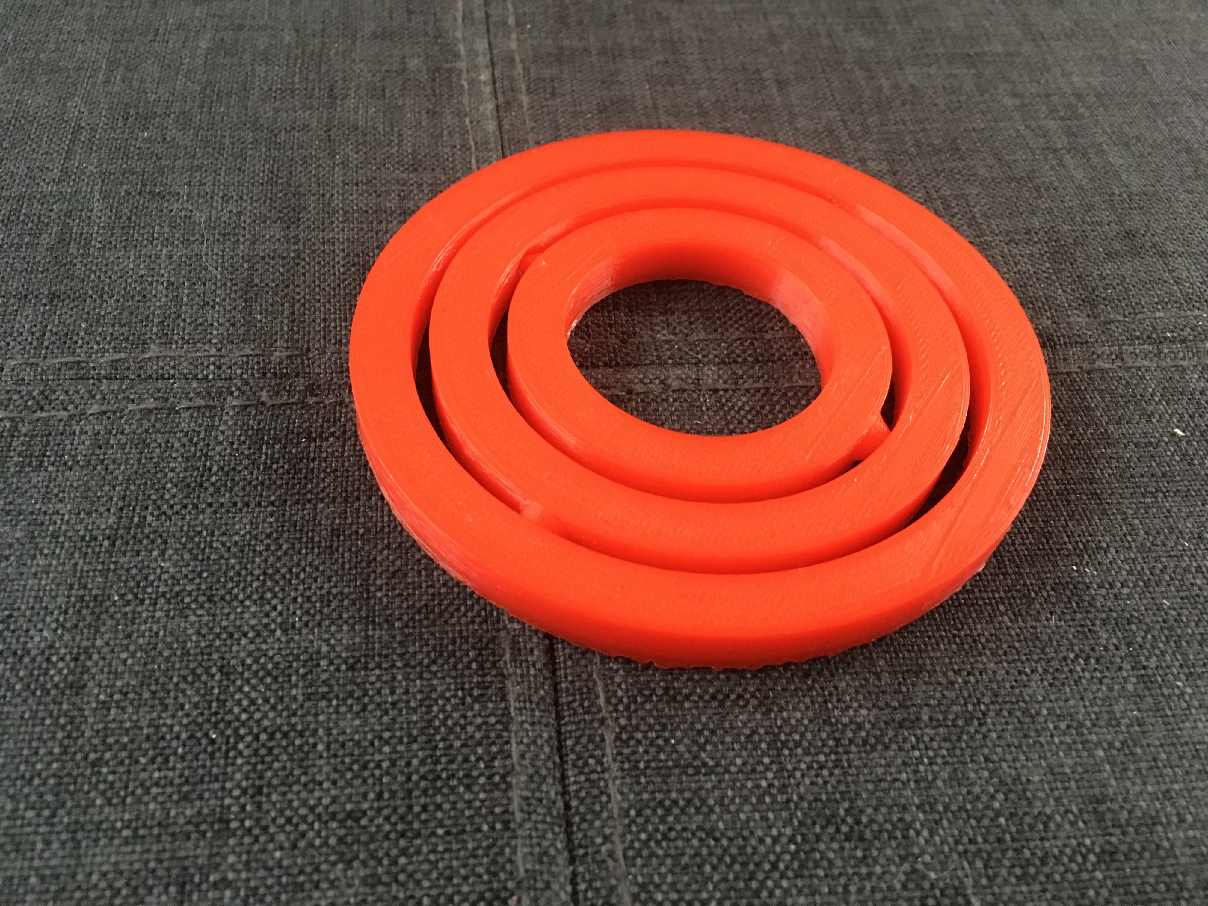
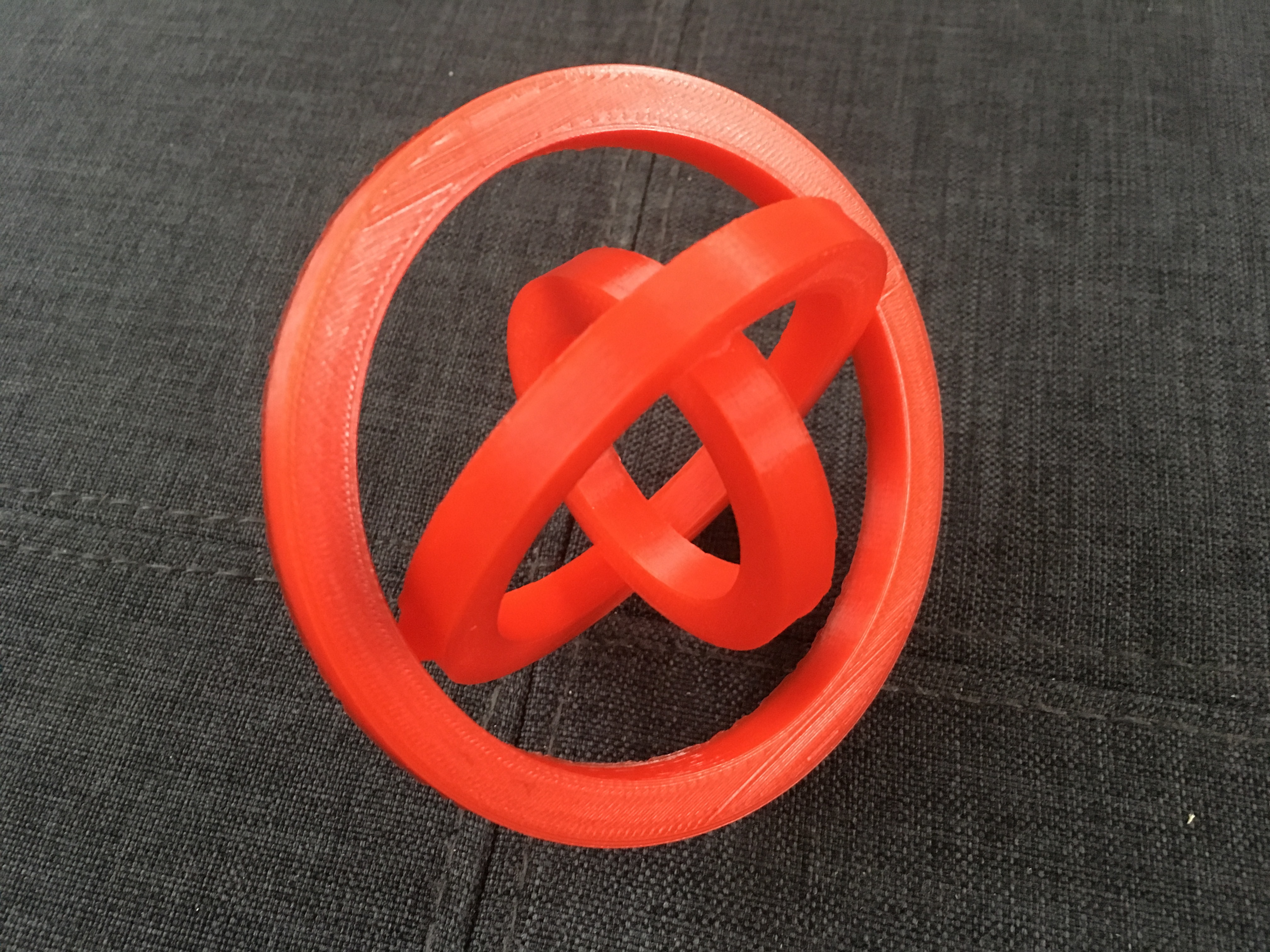
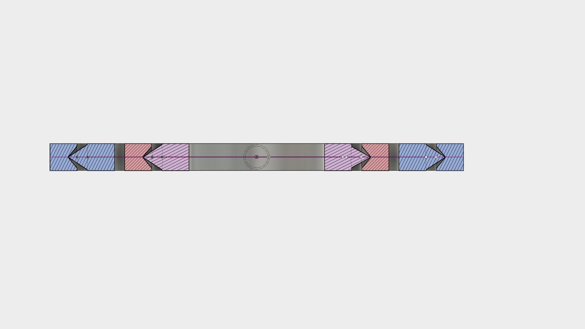
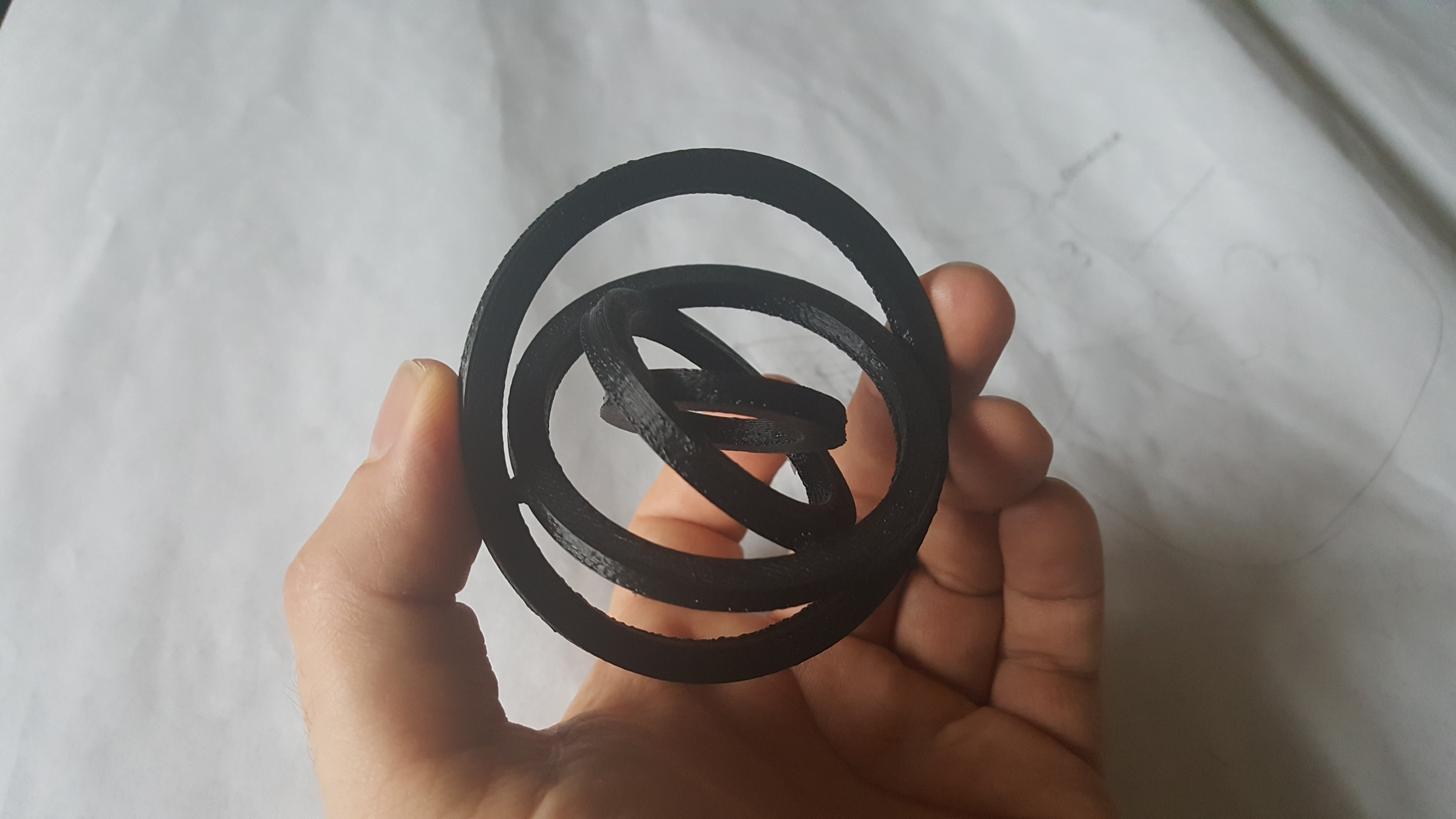
I designed it to be printed in-place as a single print, no drop-ins. The bearings are two cones at differing angles. Here’s the result:


Right off the bed it spun pretty well, and within a few minutes of spinning it it was quite smooth.

Here’s a video of me spinning it pretty soon after it came off the print bed, it now spins MUCH more smoothly than the following video.

https://www.youtube.com/edit?o=U&video_id=ckUHvZVZDRo

8 Likes

The collaboration / version control / collaboration features of Autodesk Fusion 360 are pretty slick!

@mike shared his project and I created a branch with a fourth ring.

Here is a cross section showing the bearing surfaces:

And the version I printed:

3 Likes

Awesome. How long did it take to print?

About 2 hours. I ended up speeding up the print to about 115-125% since my setting were slow and people were waiting.

The gcode is still on the tinkering sd card called Gyro*

It would be a great demo to do on open house nights, show one printing and one finished.

1 Like

How did you generate the cross-section analysis?

Fusion for anyone interested.

  1. Inspect >> Section Analysis
  2. Choose faces (I chose one of the origin planes)
  3. If desired, you can choose an offset distance
  4. Click OK

It adds it as a feature in the browser that can be shown/hidden at will. Slick.

I then used ‘Capture Image’ from the file menu to export the image.

3 Likes

This topic was automatically closed 365 days after the last reply. New replies are no longer allowed.