I’d like to start a series of “someone should” posts. These are project ideas that need a hacker to make them happen. A “someone should” post describes an idea in detail, but implies that the poster doesn’t have the time/knowledge/wherewithal to complete it. Got it? ok…
I’ve been working on fixing the laser cutter for the past few weeks, and we now have two dead laser tubes. These are large glass works of art and deserve to be on display. I would like them to be mounted on the wall behind the laser cutter. I think we could also make plaques for each tube to commemorate their service.
We have one tube that has had many many years of service, it is brown with caked-on dust and debris. We have another tube that was dead on arrival, and looks pristine. I think this tells a funny story.
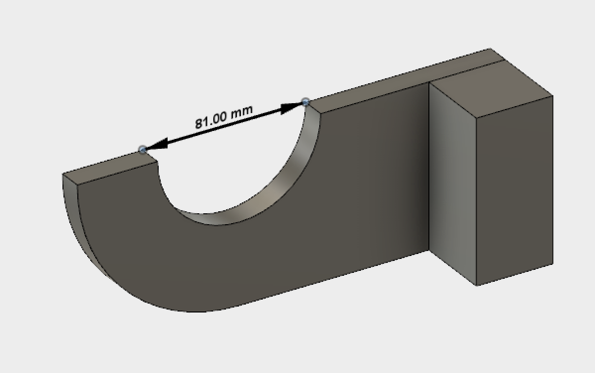
I need someone to make some wooden mounting brackets and figure out how to safely mount these to the wall. The tubes are cylindrical with a few protrusions. Their diameter is 81mm. I was thinking each tube would be mounted with two brackets like this:
Anybody want to take the lead and make this happen?
I can tell you some reasons that I would not “take the lead” on this, as a hypothetical example. First, I don’t know that you have the authority to make changes to the physical building, even if it is trivial.
Second, I don’t see anything tangible in it for me in terms of recognition. i.e. is there a badge
or something that I can earn by being part of the “someone should” program.
Otherwise it means that I have to totally buy into your vision to be motivated just by the experience
itself of the doing itself, which would be a rare thing.
Someone should implement the someone should program into the VHS portal/system and VHS regulations.
I’ll take a look at the laser tubes tonight. I have some MDF that I can use to make a couple brackets and a backboard to mount them on. Then the whole thing can get stuck on the wall somewhere…
If it looks viable I’ll add a ESP8266 some WS2812 leds to make laser like light animations and mebbe some laser sounds (pew… pew…)…
Totally fine if you are not interested. I do not necessarily expect anyone to “totally buy into my vision” and complete my project for me. Consider this an idea that I’m throwing out there for further bike-sheding, which is of course our favourite sport around here. If it motivates someone to implement the idea, great! If they take it in their own direction, great! If it motivates them to motivate me and we collaborate on it, double-great!
Great idea! I’ve mocked up some plaques which we could hang beside each tube.
I didn’t say I wasn’t interested. I am interested in both ideas. The bracket idea is pretty
simple but I am interested in making the bracket, not so much in using dead components
as interior decoration.
The second is also interesting and I just added to it otherwise it seems to be putting a brand
name on something that pretty much already happens.
Here is an update for the laser tube display/sculpture/monument/…
If you recall I tried sticking a strip of WS2812 LEDs behind it and the result seemed pretty good:
However this was laying on blanket in my workshop and probably not practical for the Space…
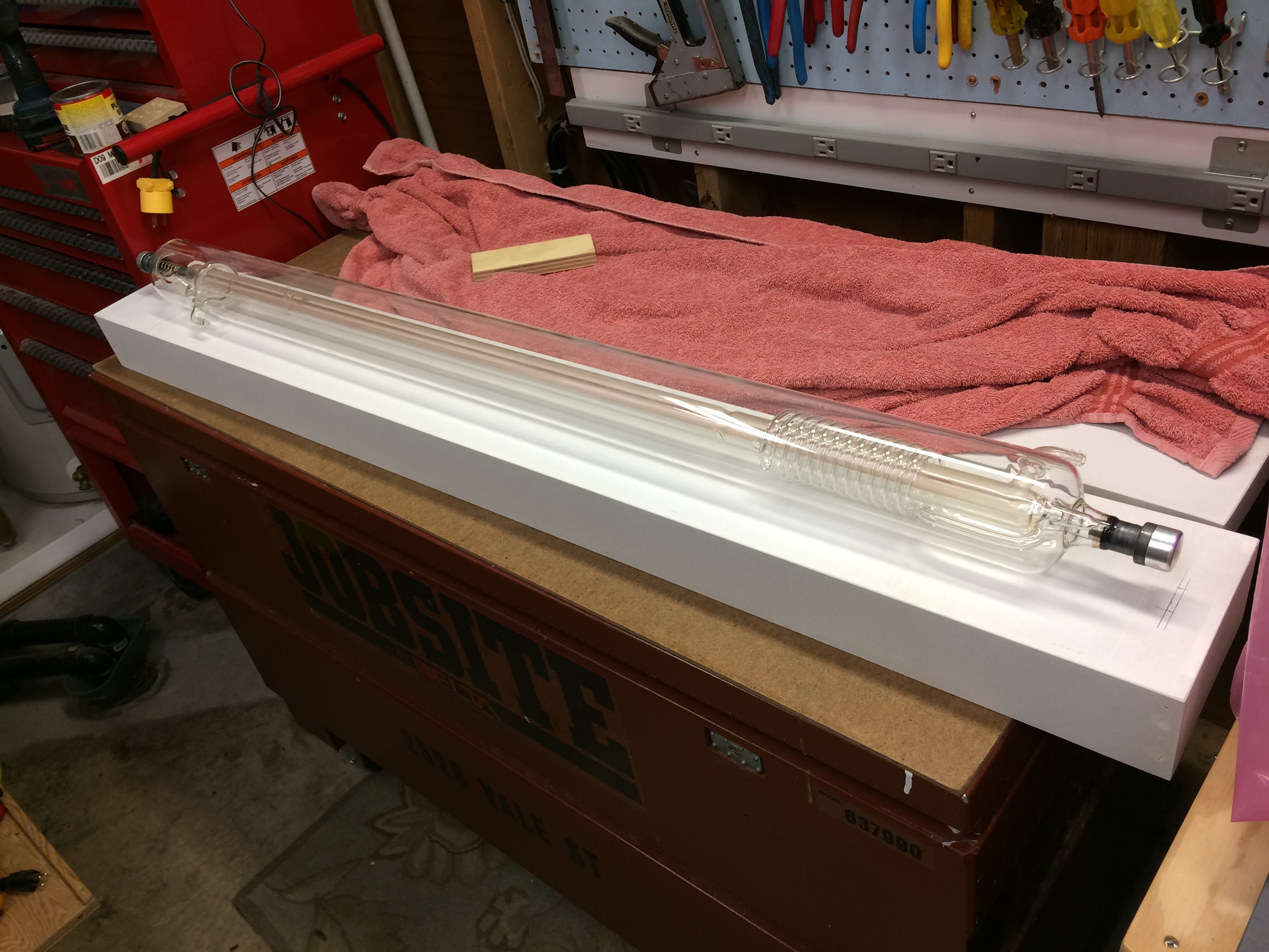
So I went about making something to mount it on…
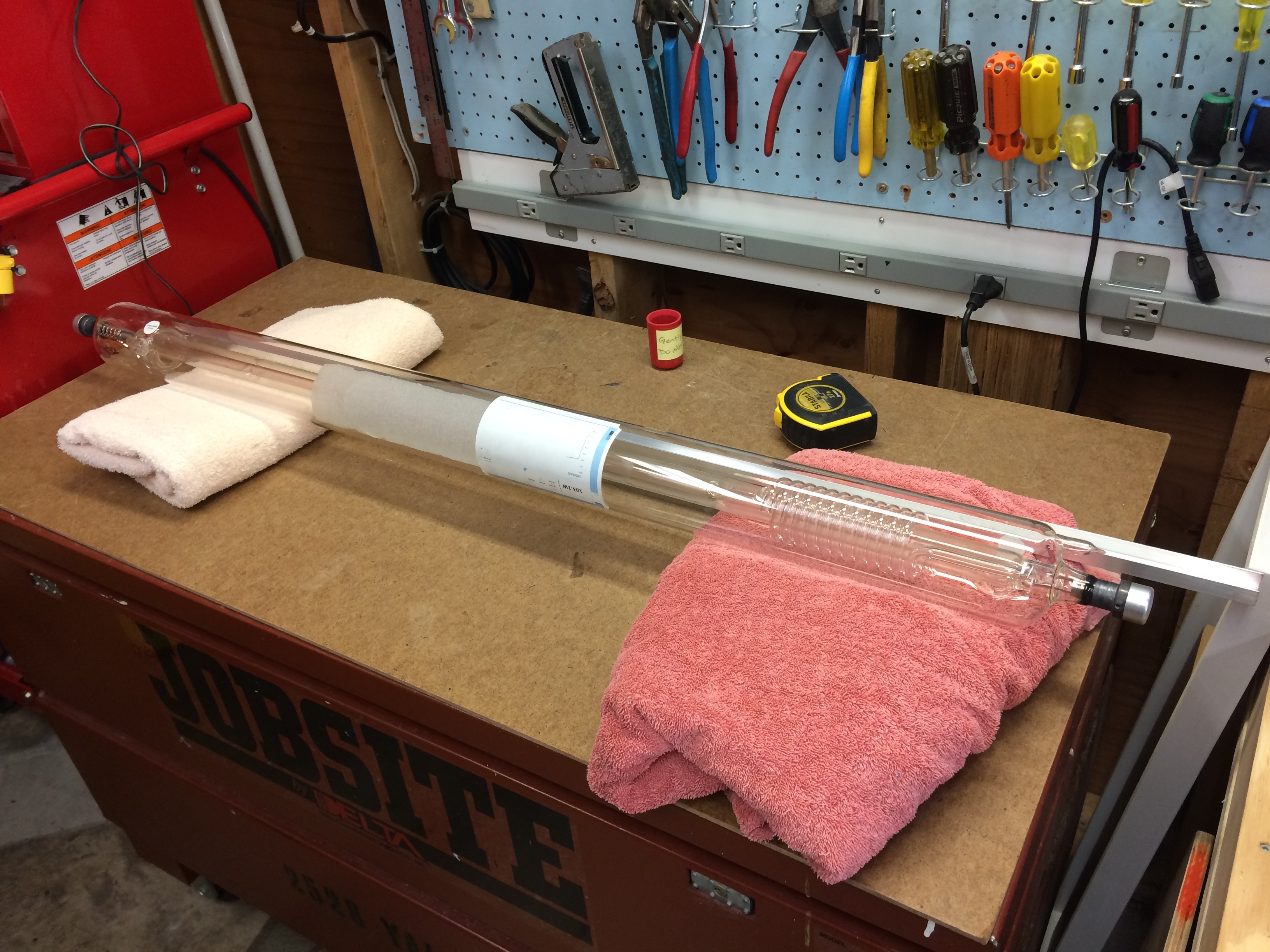
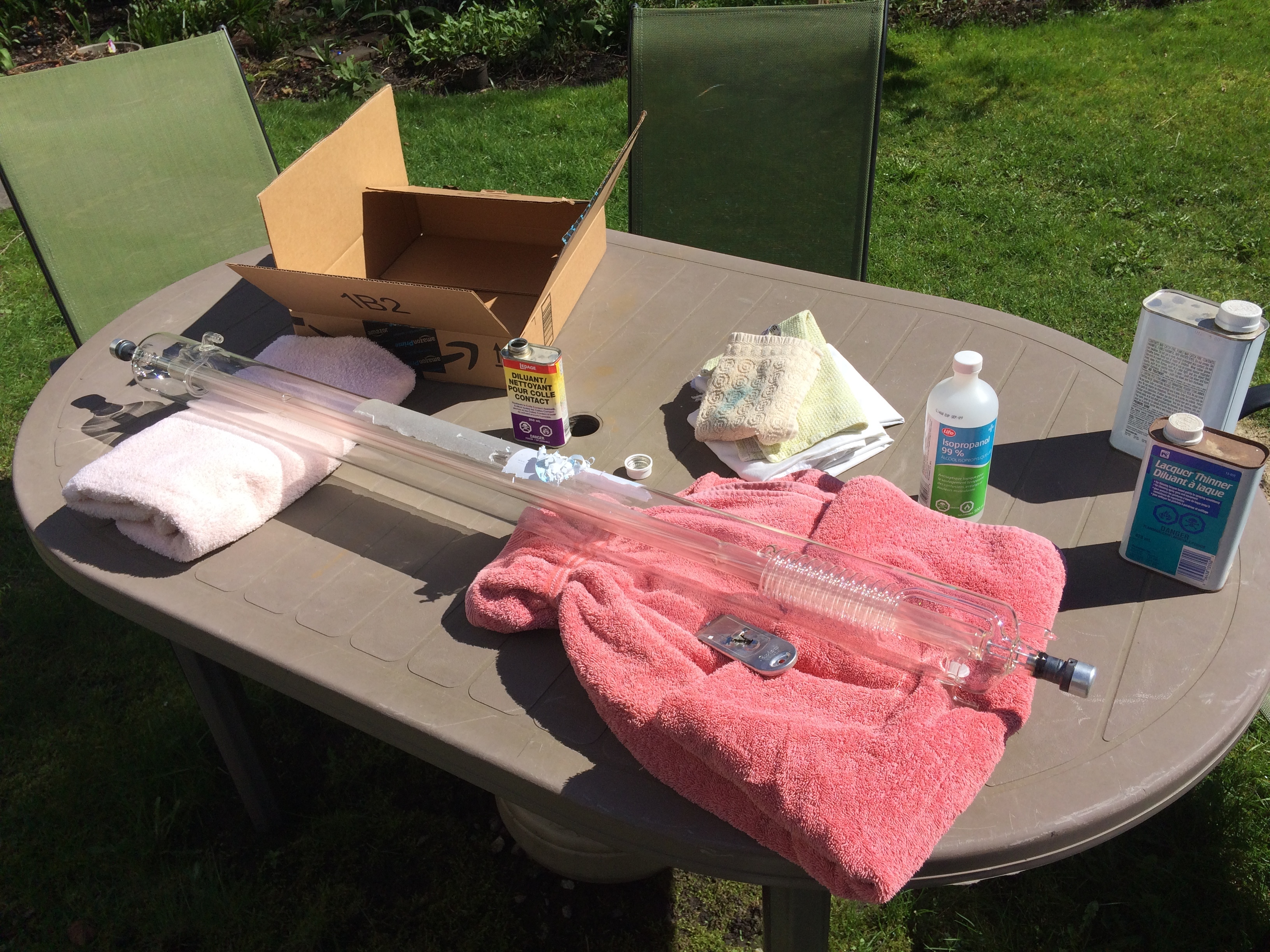
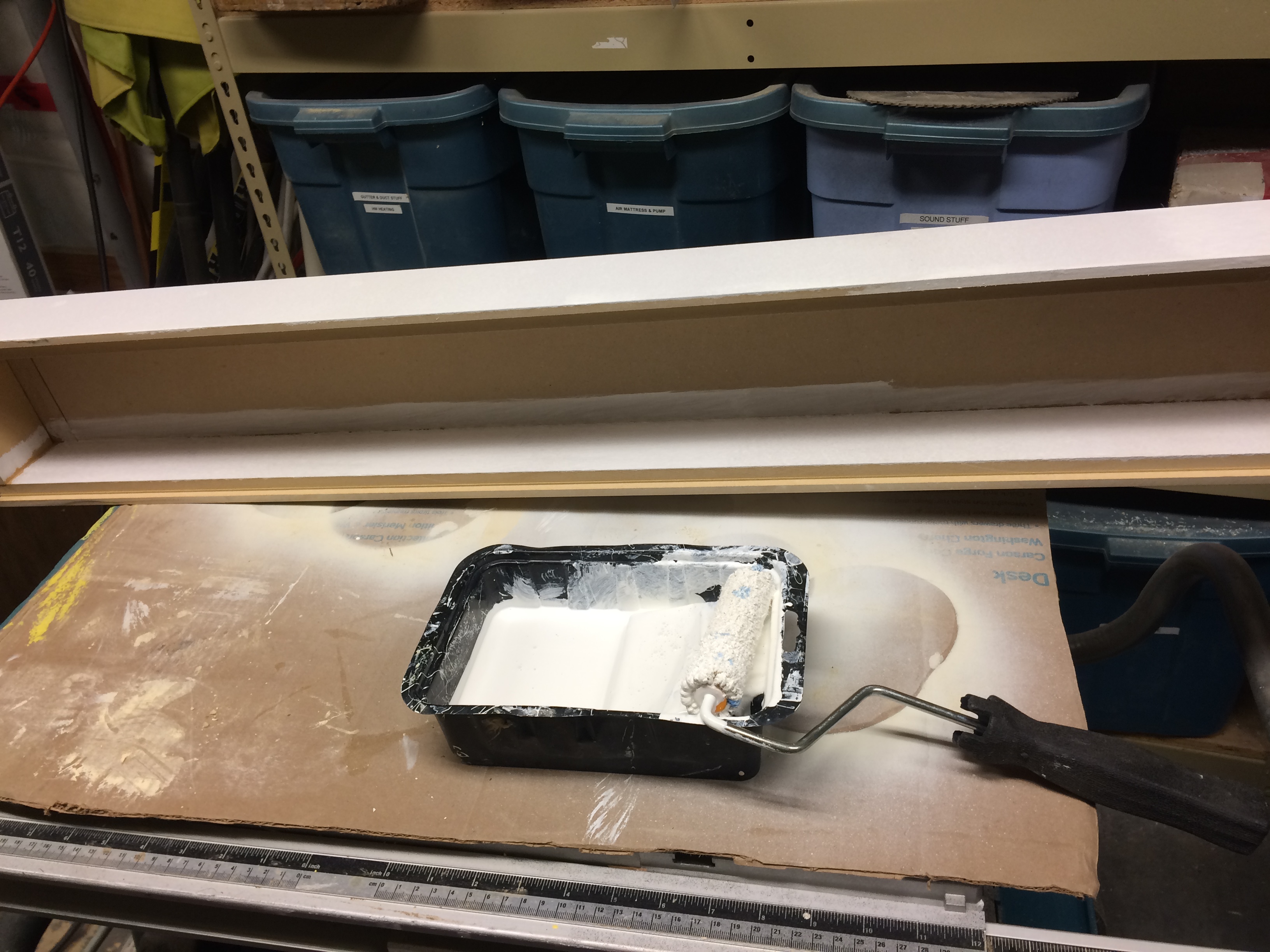
But first I had to deal with the big honkin stickers on the tube:
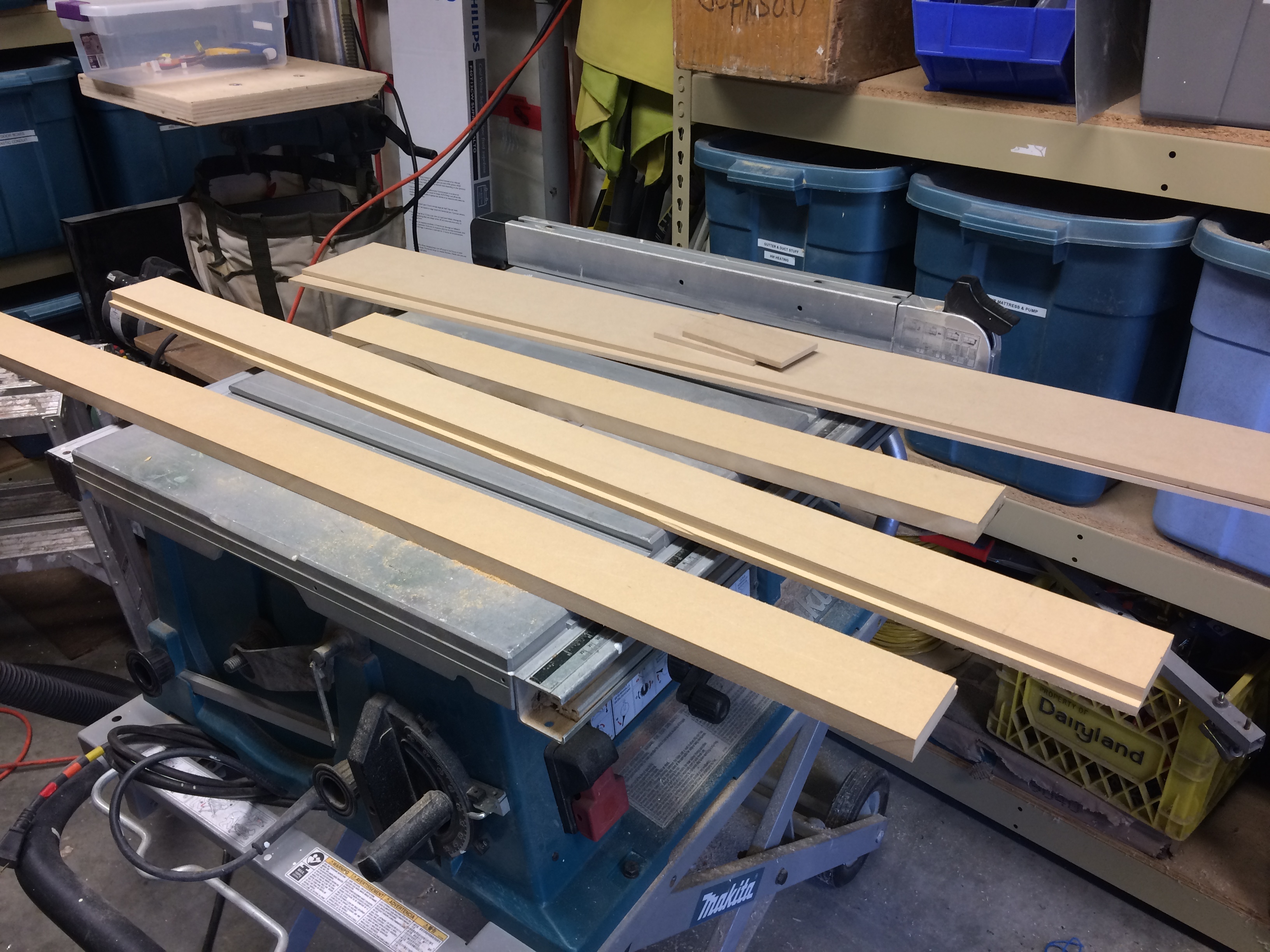
I thought about various options for a mount and figured that it would look best displayed vertically as that hides the LED strip but allows the best viewing angle. I also wanted something minimal but offering some protection and support of the flimsy laser tube. I had some MDF scrap in my garage so started cutting it up:
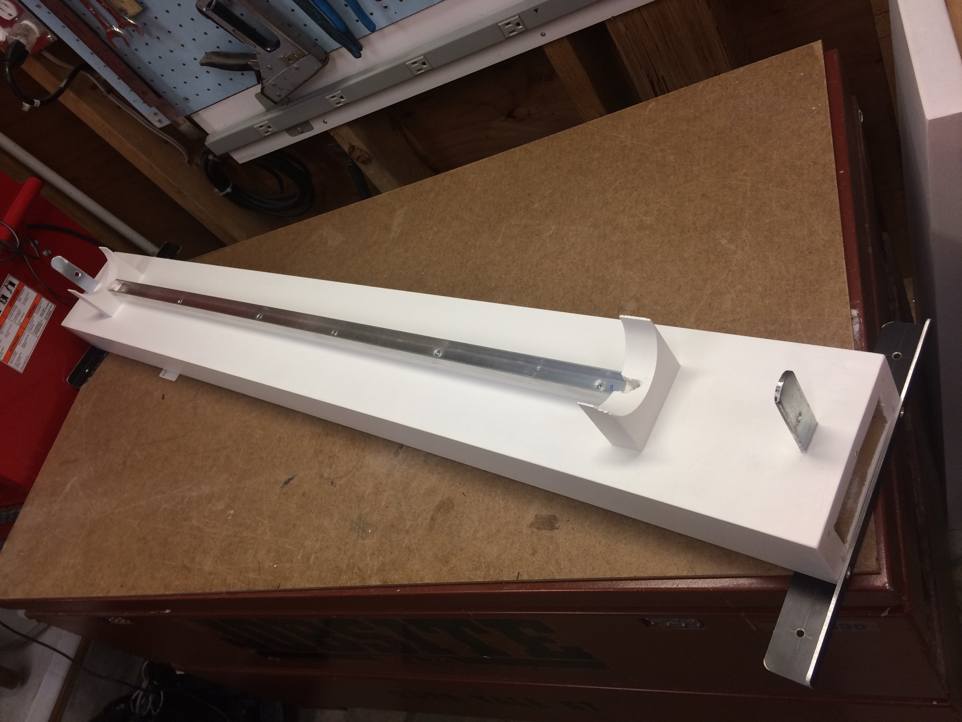
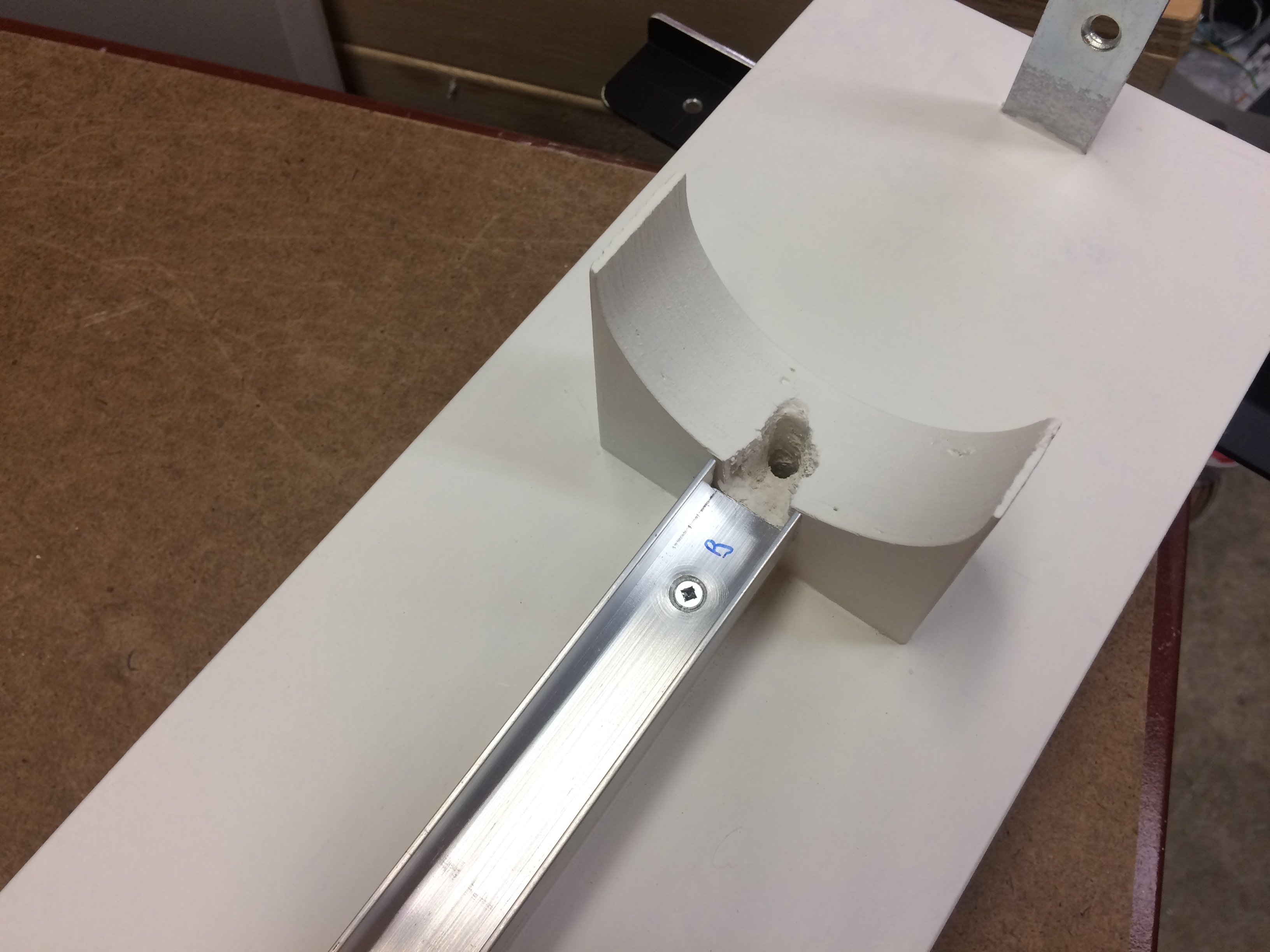
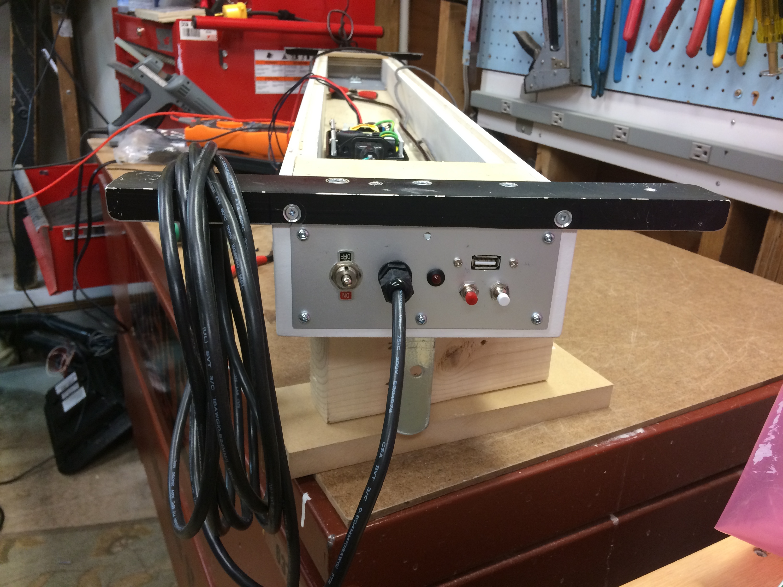
This gave me a base for mounting it that had room for a power supply and electronics. Now I just had to make brackets to hold the tube. Unfortunately I got a bit carried away at this point and did not take any pictures. I made the brackets out of doubled up 1/2" plywood. I cut the round bit for the tube out with a jig saw and them trimmed it to shape with a small drum sander mounted in a drill press. Since I wanted the tube to be vertical I was worried about it sliding out of the brackets. So I added a couple metal L brackets on each end. The end result is this:
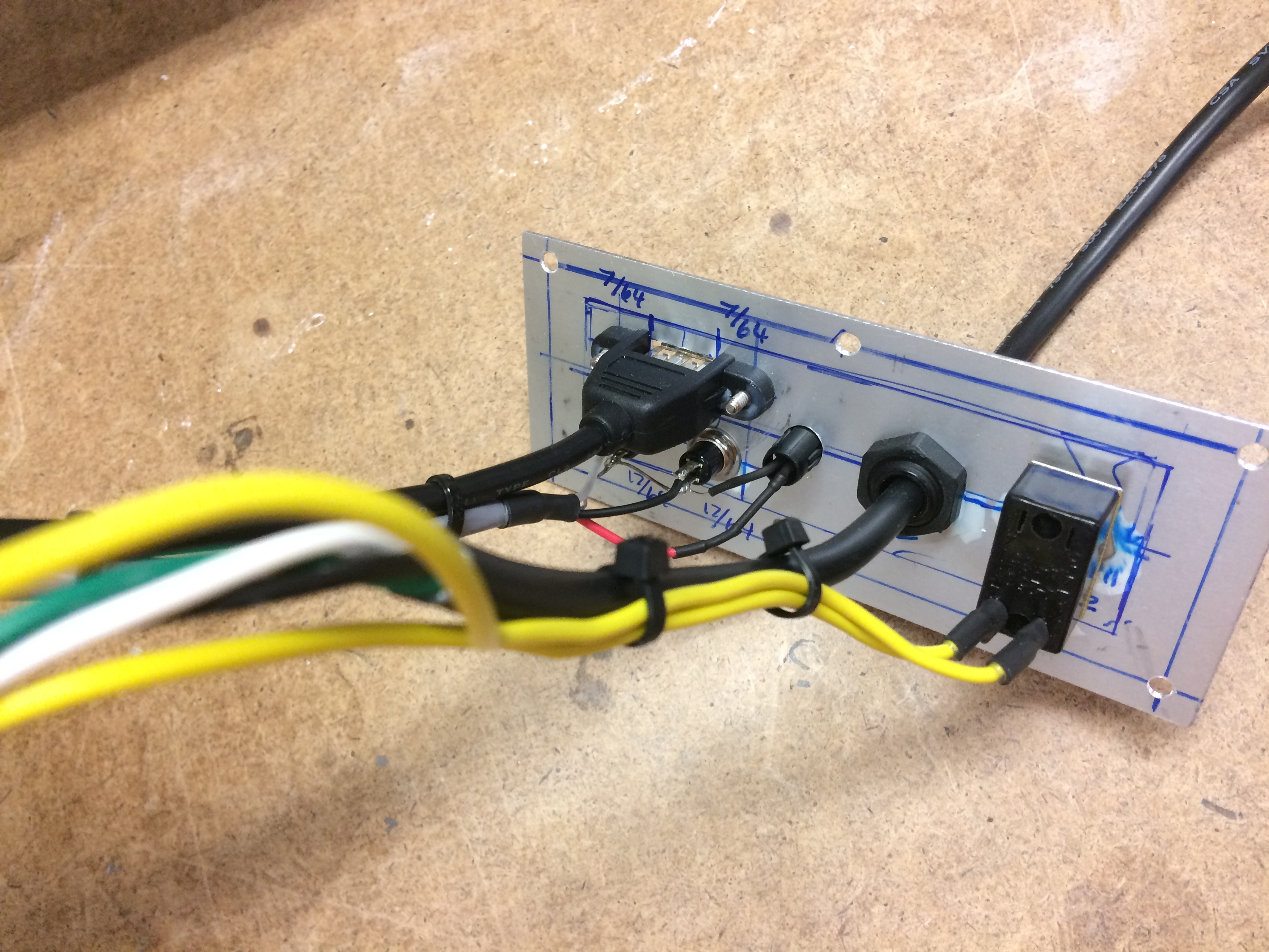
As you can see I also added some alum angle brackets at each end to mount it all to the wall. And I cut out a bit on the bottom to allow for a small alum panel for the power cable, switch, usb port and reset switches for the controller I will probably use something ESP8266 based (most likely a PartyCat or a NodeMCU)
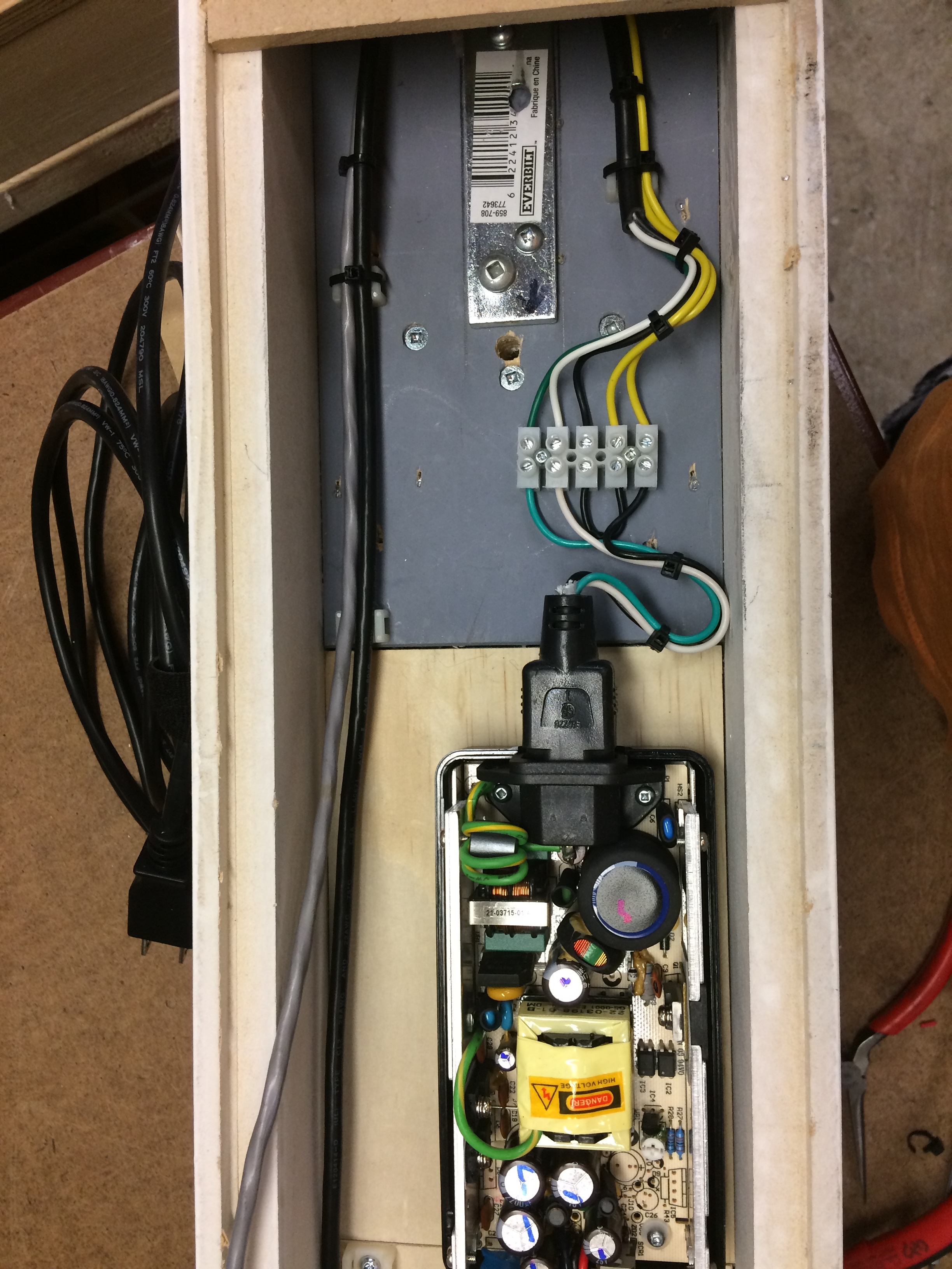
The aluminum channel down the middle will be used to mount (and hide) the WS2812 led strip. I will use a 144 led per meter strip for this to give lots of light. The intent is that this channel will almost touch the tube when it is mounted. I will then secure it to the tube with a thin bead of silicone. That and the various brackets will nicely secure the tube (though not really protect it from flying objects). The wiring will be hidden through holes in the base:
I wanted a power switch and also need to break out the reset switches and a USB connection for the controller. This will allow for easy firmware updates as my programming skills are limited and others may be able to come up with something a lot better. Allowing access this way avoids having to take the thing down and open it up for future firmware updates:
I also allowed for a led power indicator. I used shielded cable for the reset/flash switches as they are directly connected to the ESP8266 pins and are about 3 feet long (and pass by a switching PSU) so hopefully this will avoid interference. This panel mounts on the bottom end.
If you look at the back of the panel you’ll see I used some sealant (I use nail polish I steal from my wife) as a way to lock the various screws, etc into place. I will also squirt some hot glue into the led holder as I don’t find they hold the LED very well. Hot glue, clear silicone and nail polish are my “go to” glues and sealants…
Since this is meant to mount on a wall, I wanted it to have a long power cable. I also wanted something more substantial than normal lamp cord. However heavy rubber cable is really pricey and decent plug ends are also kinda $$.
I find using an extension cord is a cheap way to get something decent. Something like this doesn’t need a lot of power so 18 gauge is fine. I looked for something in white but had no luck. However I did find this at Lees:
They also had a matching cable gland that made for a nice installation:
This gives the project a long reasonably heavy duty cord…
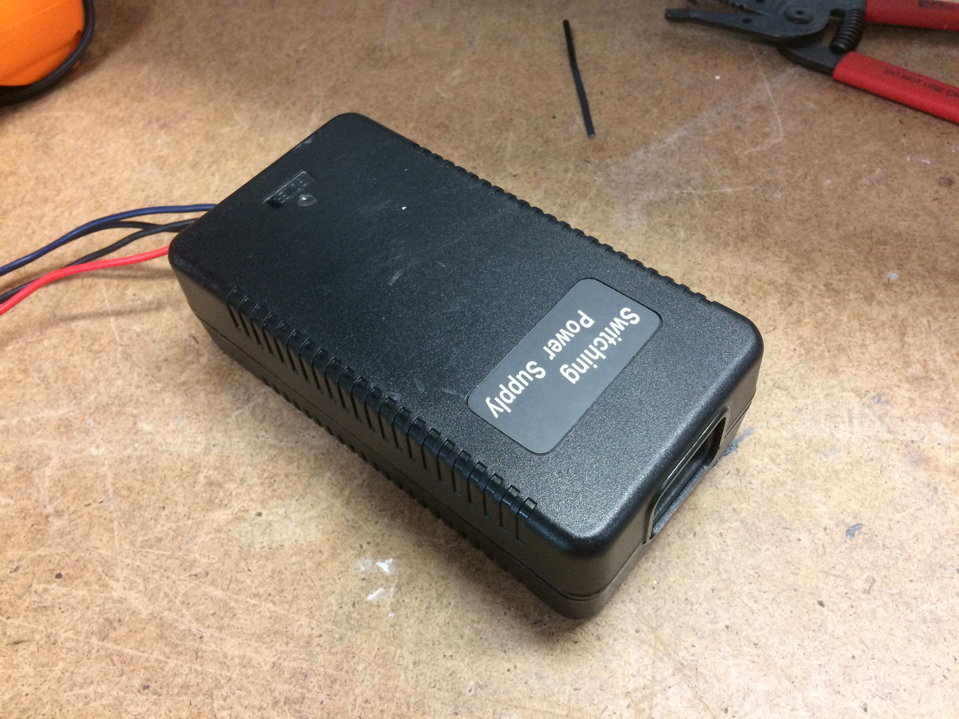
The first thing to wire up is the power supply. The ESP-8266 doesn’t need much (max draw is approx 300 mA @ 3.3V) but the LEDs can draw a lot. I will be using about 138 of the WS2812 devices. They can draw up to 60 mA each and 5 V with all 3 leds at max brightness. This is over 8 Amps. In a perfect world I’d use a 8 Amp power supply but I found this one in my garage. It has 5V at 5 A and 12V at 2A. Don’t need the 12V yet but future additions may be able to use it.
Time will tell if the power supply can supply the needed amperage. As long as I don’t fire up all the leds at max brightness it should be fine. If I end up using the FastLED library for controlling the WS2812s it has a config to limit the amperage used. If I use the NeoPixel library I will just have to be careful.
I replaced the output cable with seperate 18 gauge wires. I was tempted to remove the AC connector to allow the AC wires to be directly connected but decide against it. I used the end of a computer power cable as shown below:
I will run a bead of silicone around the connector on the power supply to ensure it can’t fall out after time.
Now onto installing the LED strip in the aluminum channel, mounting some sort of controller, writing some test firmware and then I can fire this baby up. Assuming all goes well I can then mount the laser tube and try to come up with some laser’ish lighting animations…
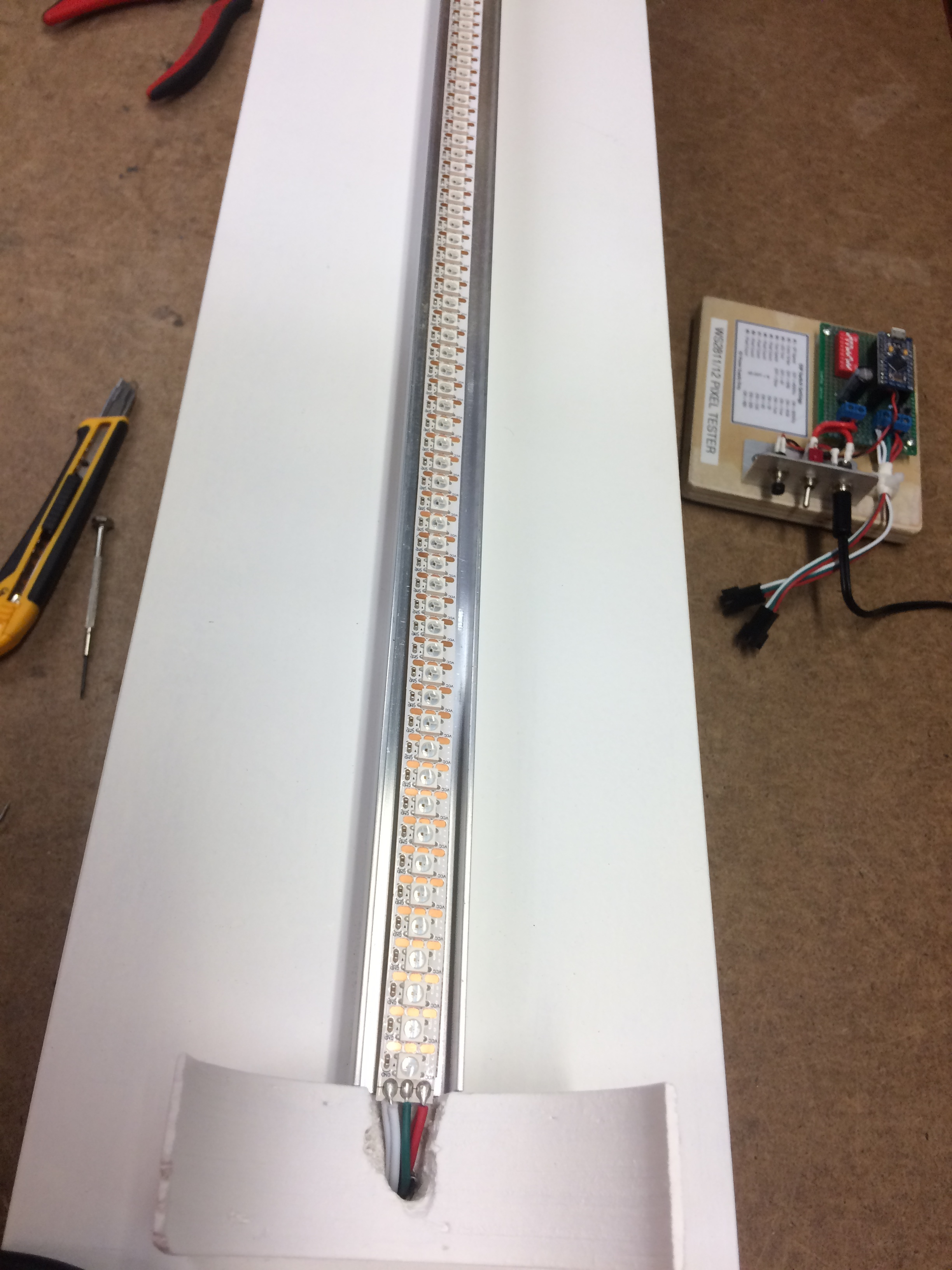
Time to mount the LED strip. I’m using a 144 per meter strip with but will cut off 6 for a total of 138… I was going to cut the connector end off (cuz it was too big to fit through the hole in the bracket) and solder on new wires when I realized I could just pop the pins out of the connector and be able to slide the wires into the hole.
Was thinking larger wires would be better but it has two runs of 22 gauge so this will work.
Now I’m wondering if I need to bother with feeding power at both ends. It a pain to solder on more wires but it will be a much bigger pain if I have to do it after the fact (if I get too much power loss through the LED strip). Better safe than sorry and over engineer things… I may still rewire both ends so the cables are long enough to reach the power supply and controller board without needing a connector.
Also thinking that the data feed to the LED strip might benefit from shielding as it will have to run about 3 feet and go past the power supply…
The 144 count LED strip are a bit harder to cut with scissors as the gap between the WS2812 chips is quite small. My first cut was crappy in that it didn’t leave enough to solder on the extra power wires. Had to shorten by one more WS2812 and now only have 137 LEDs.