Working on a Halloween project, I had an annoying problem to solve with this Arduino Pro Mini. It’s not really a problem with the board, but more with what it hooks up to.
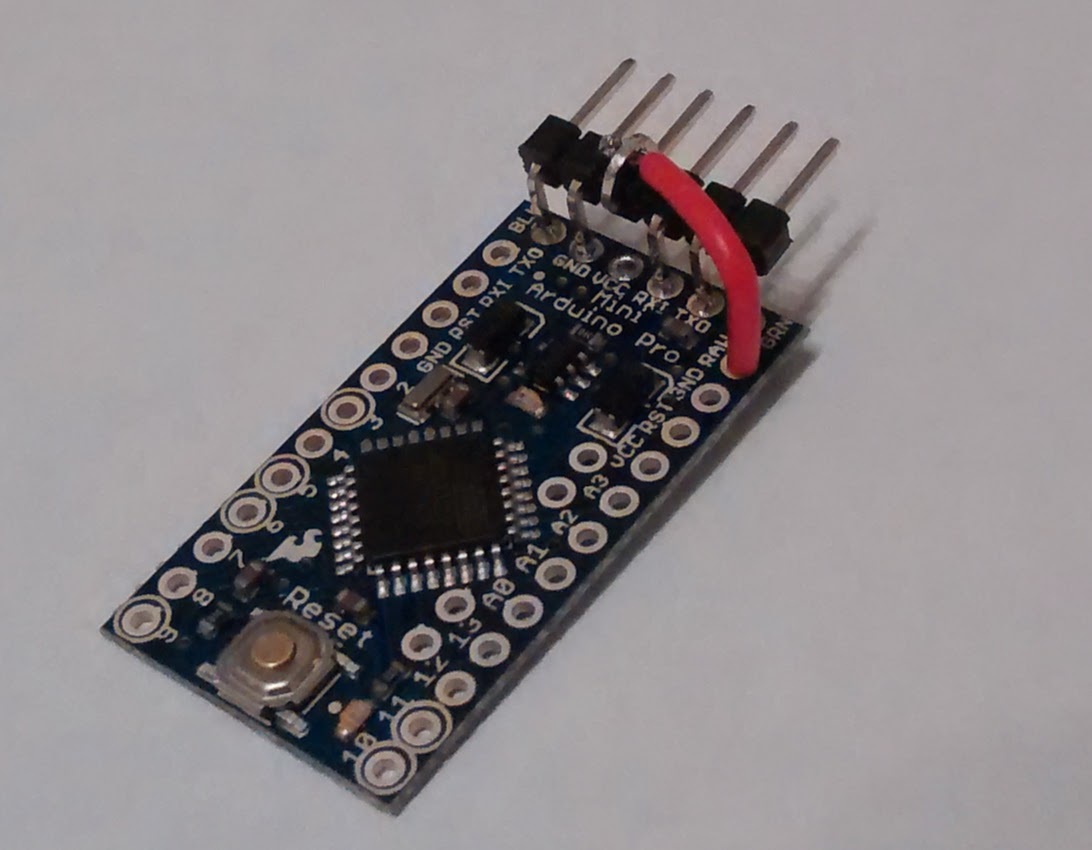
I’m curious. Looking at the picture, can anybody guess what I am trying to do here?
Sounds a bit odd, no? The board is a 3.3V Arduino Pro Mini. I have a 3.3V FTDI serial cable, which appears to be pretty common. Sounds like a match to me - and it is, up to a point.
All of those vendors mention that while signalling is 3.3V, Vcc is 5V. But they’re not all very clear about the implications of that voltage difference. It will work fine with most 5V boards, and it doesn’t cause trouble for that 3.3V Pro Mini either, since its microcontroller works just fine if you raise Vcc to 5V. Unless, of course, you’ve wired up your board to 3.3V peripherals like accelerometers, for example. Some of those can get pretty expensive, and they often contain exclusively 3.3V magic smoke.
Therefore, my Pro (mini) tip: If you buy a 3.3V FTDI cable, think carefully about how you’re going to use it with your projects!
so I’m still a little confused, and I also have this exact situation on a project I’m undertaking shortly; To clarify:
I have a 3.3v pro mini, and a 3.3v peripheral which i’ve been warned will fry at 5v VCC. if I do what you’ve done here, I ensure that I can program my arduino with any 3.3v FTDI, even if it provides 5v?
If you have an FTDI adapter board, as opposed to cable, it may have either matching Vcc and I/O voltages or selectable voltages. It’s just that one common “not quite 3.3V” cable that can cause trouble. (Every 3.3V FTDI serial cable I’ve seen has 5V Vcc, so if you’re only ever using FTDI cables, the answer is probably “yes”.)
The hole I ran that red wire to connects to the input of an on-board regulator, so the 5V Vcc is regulated down to 3.3V for the board and any peripherals. But if your serial cable or board provides 3.3V Vcc, you do not want it wired that way because the regulator will drop Vcc on your board down by whatever the regulator’s dropout voltage is.
It’s kind of annoying that there’s no single, clear solution here. Everything depends on the exact parts you are trying to fit together.
As I understand it this is a thermal issue. They don’t have room in the back of the connector for the cooling needed for a regulator. I was surprised by this too.
I prefer to power boards separately with current limit