Minimalist bed frame-platform

Tired of banging my shins on the legs of my bed, I decided to build my own bed frame. The old frame was wood, with the wood beams on the outside of the mattress and the legs attacked on the outside of the wood beams, so including the legs, the bed frame was 7" wider than the mattress and 3" longer (beams were 1.5" thick and the legs were 2" x 2").

I spent several weekends searching for bed frame designs, and found several elaborate designs or ones that were too basic and/or ended up with a frame rather larger than a mattress. I have an orthapedic mattress that does not require a box spring, so can lay on slats or a hard base. However, a box spring is the same size as the mattress, so I am wondering why wood bed frames are almost always several inches larger than the mattress.

With space at a premium, I wanted a minimalist bed frame/platform that was the same size as the mattress (queen size in this case), but also provided 24" height of storage space underneath.

Having given-up on designs that I could find online, I decided to design my own bed frame.

This bed frame design was driven by three prime objectives:

(1) no bigger than the mattress (80" x 60") so as not to unnecessarily occupy more space.
(2) simple, functional, utilitarian, yet elegant in a minimalist sense.
(3) create usable storage space underneath, ideally 24" or so.

Originally, I planned to dowel and glue together two 2" x 4" pieces, or maybe a 2" x 4" and a 2" x 2" to form an “L” section leg where the thickness of the two parts was equal to the thickness of the side and end beams (2"x6" with finished 1.5"x5.5").

Later I realized that I could achieve the same “L” cross section by making two full length cuts in a 4"x4" (finished 3.5"X3.5") to produce (already cut and ready to assemble now):

(a) an “L” section main piece with OD equal to 3.5" (as before) and the thickness of each flange of the “L” equal to the finished thickness of the side and end beams (1.5")

(b) a nominally 2"x2" piece of the same length as the original leg. Actually, a saw cut smaller, probably about 1 7/8" square. This piece has been set aside, possibly for subsequent mill work and reattachment after the folded “T” bracket is screwed to the inside corner of part (a).

Then, at one end (top end) of each “L” section, is cut a flange 5.5" from the top edge (equal to the height of the beams), nominally 2" deep (keeping 1.5" to the outside corner).

(1) first two cuts formed the “L” section and a nominal 2" square off-cut (set aside).

(2) second cuts created 2" deep shoulders on both directions to support the side and end beams.

The outside dimensions of the assembled bed should be 60" x 80".

Since the end beams are 57" long and the side beams 77" long, then the total outside dimensions will be beam length, plus 1.5" at each end (+3" total).

Since the outside of the bed frame is the same as the dimension of the mattress (60" x 80"), I will secure 1" x 1" angle irons on the inside of the side beams at a height, such that the top surface of the slats will be about 0.25" below the top edge of the side/end beams. That way, the slightly proud side/end beams will tend to centre the mattress on the bed frame/platform.

So, I have the wood cut and dimensioned, I just need the corner plates / brackets to hold the legs and the side/end beams together securely to form a strong and stable bed frame/platform.

To secure the beams to the legs, I am looking to have a folded “T” plate aproximately 12" x 12" … with the vertical (with a 90 degree fold down the centre) screwed to the inside of each leg and the ends of the horizontal arms screwed the inside of the ends of the beams.

As far as I can see, there are two ways to form this bracket:

(1) Cut “T” from mild steel sheet. Drill holes for screws using drill press, then use sheet metal hand brake to put a 90° fold down the (vertical) centre line of the “T” plate. Nominally, I was thinking to start with a 12" wide, 12" tall “T” plate, with the stem and arms about 3" wide and the steel maybe 1/8" thick.

(2) Take a large steel angle iron, maybe 6" x 6" in 12" length, then cut out two pieces on each side, about 9" from the bottom and about 4.5" from the edge. This would form a folded “T” bracket, but without the need to fold the metal (since it started as an angle bracket).

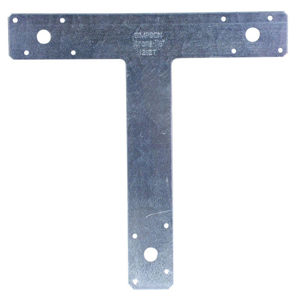
Meanwhile, I found a “T” plate at Standard Building Supplies in Burnaby, 12" wide and 12" tall, see:
https://www.strongtie.com/shapes_specialtystraps/tandl_productgroup_wcc/p/t-and-l

The specific “T” plates I have are 14 gauge (a bit thinner than I planned) and only 2" wide and 2" for the arms (top of the “T”) … whereas I was looking for 3" … so maybe a little narrower than what I had in mind.

Since the side and end beams are 2" x 6" (1.5" x 5.5" finished), I could accommodate 3" wide stem and cross bar on the “T” bracket.

Since these brackets are critical to the strength and stability of the bed frame, I would like to maximise the dimensions, within reason.

The wood is now cut, I have the slats from the old frame, plus the centre beam (aluminium box channel), all I am missing now is the corner brackets.

Mike Taylor (membership) found a small hobby hand brake that could probably fold the 14 gauge T brackets that I have, but I am unsure if it could successfully fold (say) 1/8" steel plate.

Does anyone have any suggestions? :smiley:

Or, maybe it would be easier to look for 6" x 6" angle iron (4 x 12" lengths), then cut out the excess metal.

Anyone with any thoughts? :grinning:

I would have uploaded PDF diagrams of the wood legs and the metal plate concept, but as a new member, it seems that I am not allowed to upload files. :unamused:

Peter
~~

2 Likes

Yes, that’s a function of Discourse, the forum software we use for Talk. I’ve bumped your account level from 0 - new user to 2 - member, so you should be able to upload PDFs now.

1 Like

Thanks Bruce, Peter

Here are the files that I wanted to upload…

(1) Diagram of the leg, showing the cuts
bed frame - leg v1.pdf (748.8 KB)

(2) Design for corner bracket (assumed to be cut from flat sheet metal)
bed frame - corner bracket design v1.pdf (16.6 KB)

(3) The “T” brackets that I bought (1212T) … least desired option.

Considering the options, my gut feeling is that, in terms of strength and stability, the priority among the three options are (starting with most preferred option):

(1) Angle iron (mild steel, I assume) of 6" x 6" (possibly 8" x 8") with 12" length (possibly longer)

(2) Custom bracket, maybe 1/8 inch, as per design diagram.

(3) Simple fold of the off-the-shelf 1212T bracket.

So far, I can find 1.5" x 1.5" angle iron, but not larger. I will hit the phone lines Monday morning to call the trades. Someone suggested I try Metal Supermarket (Burnaby & Richmond), who apparently sell small quantities of metal, most trades require a commercial account and/or have minimum purchase requirements. Also, I will try HD Supply (Terminal Ave), Pacific Fastners and Downtown Custom Metal Works.

Any leads on small quantity (4’ or 6’ in single lenght or, ideally cut into 1’ or 18" lengths) on large (6" x 6" or greater) angle iron are most appreciated.

Peter
~~

That brake is only good for up to 22ga unfortunately - it’s very light-duty. Your best bet if you need to bend 14ga is likely a hammer and anvil, as you need a very heavy duty brake to go that thick.

Our brake (well, we have the 18" version, but the specs are the same if you look at the manual): http://www.grizzly.com/products/30-Mini-Mighty-Bender/G9952
The only brake Grizzly sells that can do 14ga (and is almost $3k!): http://www.grizzly.com/products/48-Pan-Box-Brake-12-Gauge/G0542

In light of that, your idea to use angle iron seems like the option to go for! You could also weld the bracket together from the two halves.

1 Like

Thanks Richard. I will pursue the angle iron approach, or maybe weld two L brackets together.

From what I can find online, angle iron of various thicknesses for L 6" x 6" are availble (5/16" and up). L 8" x 8" generally starts at about 1/2" which is clearly excessive, even 1/4" is thicker than what I had in mind … but as the angle iron “legs” get longer, the material is thicker, even if I don’t need it for this application. Probably, 1/8" is sufficient, but if I am looking for 6" x 6" the material is commensurately thicker.

I will call suppliers Monday morning. If I can find supply (4’ to 6’), ideally cut into four equal lengths; what cutting options do I have a VHS? I could use a metal hack saw, but that could be tedious. Do we have equipment that could cut 5/16" or so? If not, what thicknes is feasible?

If I weld two brackets, then I could buy off-the-shelf “L” brackets … but it has been a few years since I did any welding, and I have not yet been certified by VHS. If I do the latter, is there anyone willing to assist me to weld four sets of two “L” brackets?

Many thanks,

Peter
~~

We have a couple of horizontal metal bandsaws that’ll be able to do it fine - it’ll take some time of course, but the nice thing about horizontal bandsaws is that they’re automatic (gravity fed) so time is just a matter of waiting. :slight_smile:

CC @Rob_MacKenzie

It seems that, probably, the 6" x 6" angle iron is the better solution. However, the minimum thickness is 3/8" (0.375" or 9.525 mm). I assume that if the band saw can cut 5/16" (0.3125" or 7.9375 mm), that the band saw can handle that too. Am I right? :smile:

1 Like

Yup! Those bandsaws are great, they can handle a surprising amount, slow and steady. If you haven’t used one, get somebody to lend a hand.

The welder is now fully stocked, everything needed to weld is at VHS.
We’re gonna figure out procedures real soon, in fact, tomorrow we’re going to be doing a bunch of tests. I can for sure help you weld a few brackets, no problem.

1 Like

I will probably go with angle iron. I’m hoping to have the 12" lengths of 6" x 6" angle iron this afternoon. If so, would there anyone in to let me in and help me get going this evening? I have machine shop, wood shop experience, but I would appreciate guidance as a VHS newbie.

1 Like

Still waiting for a couple of steel quotes, so it looks like I will be doing shop work Tuesday afternoon/evening…

What ever happened with this? I never was able to figure out the design you were going for based on the drawings, I was hoping to see it come to life.

1 Like

Hello Richard,

I am modifying a high density matt black MDF 19" stereo rack with mahogany
trim.

It came with one fixed shelf and three loose shelves, however only 6 1/8"
holes on a 1 ru spacing.

I have 12 new brass pins (the style with small 90° angle brackets. I have
milled the shelf sides to accommodate the new brackets.

Next I need to drill new 1/4" holes on a 0.5 ru (7/8") pitch to allow me to
accommodate more components, including some of the newer low profile
components.

I have the mild steel strip that I want to accurately drill to use as a
template.

Ideally, I would like to do this using one of our CNC machines. I have
significant CNC training and experience, but not recently or at VHS. I am
signed up to the next CNC training course…

Meanwhile, do you have any suggestions?

I do know that there are dimensional limits, particularly on the range of
movement in one pass. Can you advise what those limits are (I looked at the
machine Wiki, and found copious safety warnings, but not working limits).

I realise that I would probably have to do in two or three passes to
overcome the range of movement limits (recalibrating after sliding the
steel after each pass).

Possibly, I may have to shorten the 24" template to get around any had
limits on the length of the steel being drilled or milled. I can do that if
necessary, but I prefer not to.

See attached PDF for details on the drilling required to make this
template. As you will see, this is a fairly simple job, just drill, slide
7/8", repeat 22 times.

Comments or suggestions?

Thanks in advance,

Peter :sunglasses:

stereo rack - drill hole template v2.pdf (112 KB)

This topic was automatically closed 365 days after the last reply. New replies are no longer allowed.