I found @TomKeddie’s video pretty interesting, I’ll re-watch it next time I have to hand-solder any SMD bits. ![]()
Wow this board looks real good! Im going to keep an eye on this for when my vape mod is done.
I’m amazed at the surgeon like smoothness of @TomKeddie 's hands in that video @Arrgh posted. I think mine would have vibrated the chip off the board…
1 Like
Hi @lukecyca (or anyone with a working PartyCat!). Finally completed my PartyCat (hand soldered) and things look promising but I cannot upload the partycat-blinky sample code. Hopefully the issue is just a configuration problem.
The PartyCat is powered by a 5V 5A PSU and the red LED is on. The Arduino has the ESP8266 library installed plus the WS2812_i2s library.
The 5V FTDI cable was purchased from Lee’s and looks identical to the Sparkfun example you provided, down to the same colour of wires in the same order. The orientation of the cable is the black wire is connected to the GND pin.
When I open the Windows Device Manager and watch the “Ports (COM & LPT)” section, “USB Serial Port (COM6)” is added successfully when I plug in the FTDI cable. I confirm this is using the default FTDI driver and the default port settings are 9600 bps, 8 bits, no parity, 1 stop pit and no flow control.
In the Arduino IDE I choose the board “Generic ESP8266 Module”. Is that correct? When I do that a whole bunch of default settings appear, as shown here…
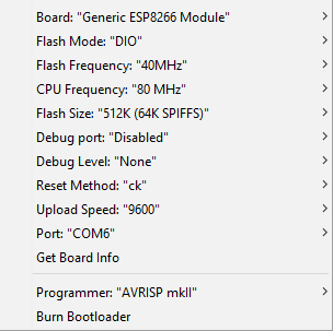
The Upload speed was originally 115200 bps but I changed this to 9600 to match the COM6 port settings. Should anything else be changed?
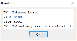
When I choose “Get Board Info” in the Arduino IDE it displays…
I put the PartyCat into programming mode by pressing and holding the PROGRAM button while pressing and releasing the RESET button. Does the LED provide any indication that the PartyCat is now in programming mode?
The partycat-blinky sketch compiles successfully but when I try to upload I get the following messages:-
warning: espcomm_sync failed
error: espcomm_open failed
error: espcomm_upload_mem failed
I also tried changing the Arduino and COM6 port settings to 115200 bps but with the same results. Does the PartyCat LED flash when uploading?
Any ideas are welcome.
Kind Regards
Ian
1 Like
Debugging issues like this can be super annoying. My best suggestion is to come to the space and use someone’s existing set up to verify that your board is working.
As for solutions, first, the esp is 3.3 volts, careful with 5. The ftdi needs to be 3.3.
Next, you flash at 115200.
1 Like
I was just programming my Partycat the other day.
The cable I got from Lee’s is the 3.3V io FTDI cable (This cable has 5V on the VCC).
3.3V io pins FTDI cable from Lee’s Electronics
I also had programming issues so I downloaded the latest Arduino IDE.
I just checked my config and it appears that I have the Generic ESP8285 Module selected. Interesting.
1 Like
Uh-oh… The FTDI cable linked to in the PartyCat instructions is https://www.sparkfun.com/products/9718 which is the 5V version and not the version with 3.3V I/O. Can anyone else confirm if using the 5V version would cause the programming to fail? On the one hand I hope that using the 3.3V version is the solution… (but Lee’s don’t do returns ![]() )
)
Ian
I have the SparkFun version of the FTDI cable and was able to program okay.
One step that I had a little trouble with was putting the chip into programming mode. Try holding down Program, pressing Reset, then releasing both at the same time.
I had issues programming my esp, turned out there was a short in the level shifter chip
@captain_semtex
when you ate next in VHS, i can maybe help you trouble shoot?
i got some experience trouble shooting my own board, which had multiple soldering fails
Many thanks @xsquared. I may take you up on that if other attempts fail.
Thank you
Ian
Many thanks @JDMc. Is there any way of knowing when the ESP is in Programming mode other than the upload works?
Also is there a timeout i.e. how long after pressing PROGRAM and RESET do I have to upload?
Kind Regards
Ian
As far as I recall with other ESP modules (haven’t put my PartyCat together yet) the module stays in the programming mode after you have set it till it is reset either by the upload completing or being reset…
I’ll be done at the Space one night this week (shoudl know by Monday) and can take a look at it for you…
1 Like
i think you can check via the serial monitor window in the arduino IDE
FTDI Cable
Oh no! My mistake. https://new.sparkfun.com/products/9717 is the correct one I think. I have corrected the instructions for future revisions. I’ve been leaving my cable in my (unlocked) locker at VHS. Feel free to use it for troubleshooting, but please return it after use. If you find that you fried your chip, let me know and I’ll help you rework it with a new one if necessary.
Program buttons
Think of the program button as a modifier key (shift, ctrl, etc.) like on a typical keyboard. Hold down program while you click reset. Then upload your code.
After uploading, your code will start running immediately, so it will appear to be our of “programming mode”. However if the chip does a software reset, it will still be in programming mode which in unintuitive. You have to actually power cycle (or press the RESET button) to get it out of programming mode.
Boot codes
When the ESP8266 boots up, it spits out a message like this:
ets Jan 8 2013,rst cause:1, boot mode:(1,7)
The first parameter of the boot mode indicates whether it’s in programming mode (1) or not (3).
Unfortunately when the chip cold boots, this message is sent at a weird baud rate of 77400 so it typically shows up as garbage if you have a serial console at a different baud. If your chip reboots then it will use whatever baud rate you were previously using. So you’ll see this if your ESP resets due to the watchdog timer, etc.
1 Like
Thank you everyone for your help and suggestions. Progress is definitely being made as I can now program the ESP… hurrah… but there is no output when I use the partycat-blinky sample code.
I’m not sure why the programming started to work. I must have had a short with the buffer gate IC, even though I could not see one with my magnifying glass. Nevertheless, I touched each pin with the soldering iron, et voila!
I know the programming is working because I can change the delay and the red LED on pin 16 will change its flashing frequency appropriately, plus I can also write to the serial output and see the text. The programming is done using the 5V FTDI cable… not sure if it is working out of luck and things will ultimately fail.
Anyway, there is no output to the WS2812 LEDs. I also tested with a strip of my own and no output. I placed a logic probe on the Data line and expected to see a pulse each second, but the Data line is permanently at 0V.
I fully populated my board with all the optional header pins. The 10-way header is between the ESP and the buffer gate IC, while the 5-way header is the output from the buffer gate IC. Using the logic probe I can see there is some activity on pin D3, from the ESP (RXD), but the matching output pin D3 from the buffer gate IC is 0V.
This would suggest there is still a short somewhere with the buffer gate but I double checked and when there is no power connected there is no short between the output pin D3 and ground.
Any other trouble shooting tips are appreciated. Failing that, I cannot come to the open house today, but maybe next Tuesday.
Thanks in advance.
Ian
Have you tried disconnected the programming cable and then reset the board?
I find that with the prolific cable I have, leaving it plugged in will short the data to ground.
From the partycat instructions:
Since pin 3 is also used by the ESP8266 for UART RX, unplug the FTDI cable after programming for best results driving the WS2812s.
The ESP8266’s UART RX pin is also the one used to drive the WS2812 bus (through the level shifting buffer chip). If you leave your UART cable plugged in, it can interfere by pulling the lines high (IIRC).
I find that using my cable, it mostly works but the WS2812s occasionally glitch. Once I remove the cable it works fine. This is also the reason that the first WS2812 sometimes flickers when you’re programming the ESP.
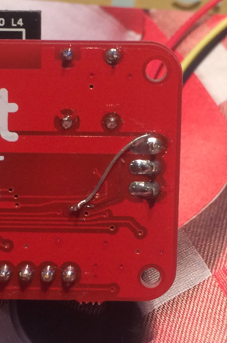
Good news… my PartyCat is finally working. I had assumed that the problem was with my hand soldering of the buffer gate SMD but I ultimately traced the problem to there being no 5V on pin 14 (Vcc) of the buffer gate. I knew the soldering was good and couldn’t work out how that was possible… until I flipped over the PCB.
Somehow the track from the 5V rail to the buffer gate IC had lifted off the PCB?! I’m clueless how that happened but replacing the track with some wire solved the problem and everything now works perfectly… including repeated programming with the 5V FTDI cable.
Thank you to everyone for your helpful suggestions.
Kind Regards
Ian
7 Likes
I’ve just updated the partycat github repo:
- Documentation PDF
- A few minor updates
- Panelized gerbers (same ones I used for the VHS kits)
Now that this revision is tagged in git, I’m going to start work on rev 3 which will be smaller and simpler and prettier.
6 Likes