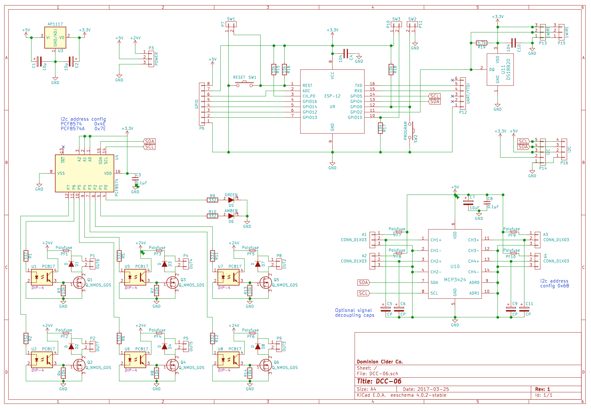
Continuing my line of custom ESP8266-based PCBs for Dominion Cider, I’m now making DCC-06. Last year I made DCC-05 and have used it in lots of projects for telemetry and some light actuation. This one is similar, but has four analog inputs, and six high power DC outputs. I plan to use this in a few projects that require much more coordinated actuation:
My bottle filler, where the analog inputs will be used for pressure transducers, and the high power outputs will drive solenoid valves.
A larger glycol chilling system, where the outputs will drive small DC brushless pumps as well as valves.
An automated keg washing machine, where valves will open and close to coordinate the cleaning cycle.
Since I’m still pretty new at making PCBs, I’d really appreciate some proofreading from our EE veterans. Your critiques and feedback on my last boards have helped me tremendously.
In prototyping, I’ve found that there is a lot of noise in my system. Likely sources are the cheap but beefy 24V switching power supply I’m using, and also driving a brushed DC motor (via an external driver board). I’ve had decent success sprinkling capacitors around, but open to more precise solutions.
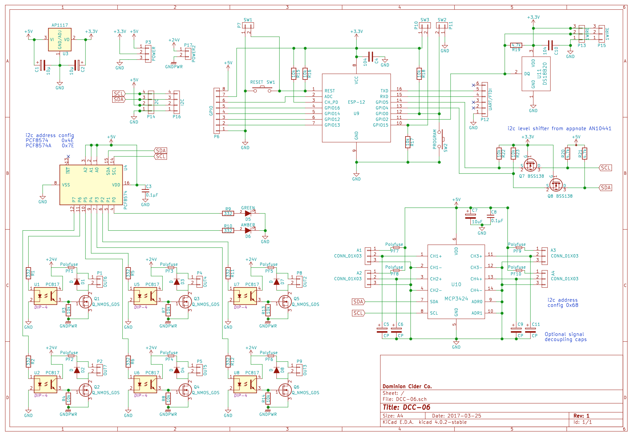
Thank you everyone! A new revision is posted below.
Thanks - added. I’ve only ever connected one device at a time (one of those 2x16 LCD backpacks) and I think it must have 5v pullups on it.
Indeed! My bottle filler is currently using Tom’s FET board, plus a bunch of other misc modules and dead-bug components. It works well but this board is supposed to amalgamate and tidy that up by removing the need for so many jumper wires between little boards.
Yeah, I will physically separate them on the board, so it makes sense that their GND pours are separate. They will will ultimately be tied together back at the power supply, but forcing them to have “home run” connections back to that point should minimize interference on the board… I am using a single large 24V PSU, plus a DC-DC converter board to generate 5V from that, then the voltage regulator on this board to get 3.3V.
There seems to be some evidence that the ESP8266 is 5V tolerant and that I could run this bus entirely at 5V. However I’ve opted to translate it to 5V and run all the slaves at 5V
Could you elaborate? Would that go on the 5V supply for the board? Or the signals somewhere? Should I just sprinkle them around like I do with caps?
You should consider a separate isolated 5V supply for your digital logic, and completely isolating it from the high power side, including the ground. This will be much easier than chasing down ground bounce issues, and you’re already 90% of the way there since you’re isolating the outputs. I’m thinking of a small onboard module like Muratra CRE1 series (check your power requirement), but you could just as easily use a separate on-line supply like a USB wall-wart. Star ground might also work, but isolating it is easier to do right and will gain you some protection for the digital side too.
I would add provision for configuring the I2C addresses (just some pads on the board you can short to set the address pins) as well as allowing full differential inputs on your ADC, instead of shorting all the - inputs to ground (short with a jumper if needed) in case you need to use a differential sensor at some point.
Just one at the 5V input. The math is more than I’ve bothered to dig into, I generally use whatever I have laying around, I think there are some in the vhs component drawers.